


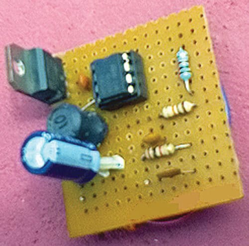
 To drive small devices like neon lamps, you need a high-voltage DC power supply. This circuit is a simple DC-to-DC boost (step-up) converter for general-purpose applications. It uses readily available parts that can be bought from any electronic components store. The author’s prototype is shown in Fig. 1. Let us design High Voltage Generator circuit for Microcontroller Projects
Circuit and working of High Voltage Generator
The circuit diagram of the high-voltage generator is shown in Fig. 2. It is built around NE555 timer (IC1), STP55NF0 MOSFET (IRF1), diode UF4001 and a few other components. Values of resistor R4 and Zener diode ZD1 are based on the voltage and current required for your application.
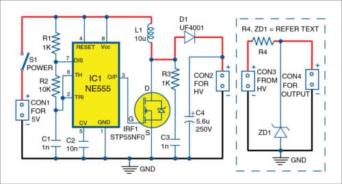
NE555 timer is configured as an astable multivibrator oscillator, which oscillates at a frequency (around 68kHz) determined by the values of resistors R1, R2 and capacitor C1. Its output directly drives a MOSFET (IRF1) that switches the current through a 10µH/200mA inductor (L1).

Fast recovery diode D1 and high-voltage capacitor C4 together provide an efficient output rectifier and filter circuit, while R3 and C3 forms a snubber network for IRF1.
Place the components in appropriate places on the PCB. Connect a 5V DC source to input CON1. Check the output voltage available at output connector CON2 using a multimeter—it could be anywhere between 30V DC and 90V DC. You may trim it for real-world applications by adding a simple Zener diode-based shunt regulator circuitry, as indicated within dotted lines in the circuit diagram. Note that, final output voltage varies with a connected load, but it should not swing by more than a few volts for a load up to 10mA.
Example
Assume that raw output voltage across CON2 is 50V (Vin), and what you are looking for is 1mA (Ireqd) at 27V (Vreqd). For this, use a Zener diode (ZD1) rated at 27V, and calculate the value of series/ballast resistor R4 using the formula given below:
R4=Vin-Vreqd/Ireqd
=50V-27V/1mA (in this example)
Values of R4 and ZD1 are based on your requirement.
This is a basic design idea for electronics hobbyists. You can modify the circuit by changing the operating frequency of NE555 IC, and/or altering component values like inductor, MOSFET, rectifier and filter capacitor, to get desired results.
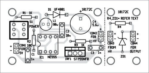
Construction and testing
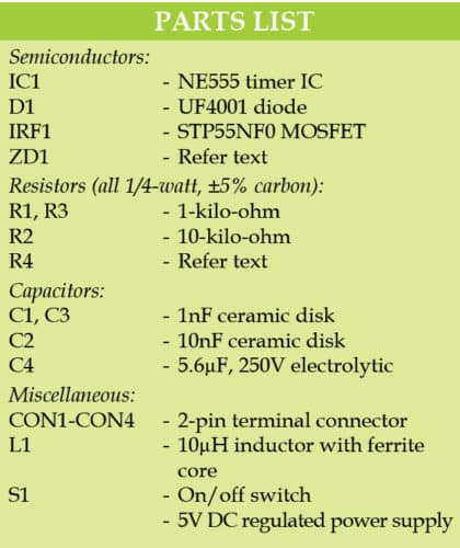
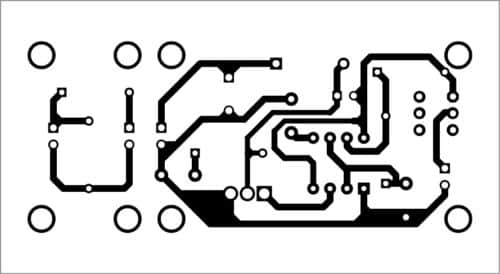
An actual-size PCB layout for the high voltage generator is shown in Fig. 3 and its components layout in Fig. 4. After assembling the circuit on the PCB, connect 5V across CON1.
Download PCB and component layout PDFs: click here
Caution
This circuit may not be as dangerous as AC mains power, but it can still shock you depending on your body resistance. So, take necessary precautions while working on this circuit.
T.K. Hareendran is founder and promoter of TechNode Protolabz

Please tell me how to find the oscillator frequency theoretically — – “NE555 timer is configured as an astable multivibrator oscillator, which oscillates at a frequency (around 68kHz) determined by the values of resistors R1, R2 and capacitor C1.
The formula for the astable multivibrator to calculate output frequency (f) is given by :
f=1.443/(R1+2xR2)C1, where resistor R1=1000-ohm, R2=10,000-ohm and capacitor C1 =1nF
New thinking, very useful circuit, in future I try to this. Thanks
You are most welcome.
very good.