 This project is based on the Android app and Arduino Uno using Bluetooth as the wireless communication medium. It is a simple and flexible home automation system with only a few electronic components, without complex soldering. This project is designed to control three appliances, but it can be extended to six or more.
Circuit and working
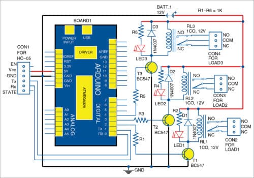
The block diagram of the home automation system for controlling three electrical appliances is shown in Fig. 1 and its complete circuit diagram in Fig. 2. It is built around Arduino Uno R3 (Board1), HC-05 Bluetooth module, three relays (RL1 through RL3) and a few other components. This project demonstrates how to turn on/off the appliances connected with the relays using an Android app on a smartphone or tablet.

Relay pin connections
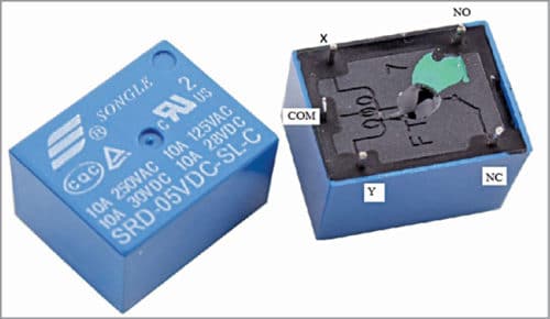
Relay connections marked as x, y, COM (common), NO (normally open) and NC (normally connect) are shown in Fig. 3. x and y are two points across the coil of the relay.
The relay board consists of relay drivers. Three BC547 transistors (T1, T2 and T3) are used as relay drivers for controlling the three appliances.
Pin 2 of Arduino Uno is connected to T1 through base current-limiting resistor R1. Similarly, pins 3 and 4 of Arduino Uno are connected to T2 and T3 through R3 and R5, respectively.
All emitters of the transistors should be connected to ground (GND) pin of Arduino Uno.
Connect VCC and GND pins of HC-05 Bluetooth module to 5V pin and GND pin of Arduino Uno, respectively. And, connect Tx and Rx pins of Bluetooth module to Rx and Tx pins of Arduino Uno, respectively.
Connect NO terminal of each relay to one terminal of electrical load, and the other terminal of the load to neutral (N) line of 220V AC mains power supply. Connect live (L) line 220V to COM terminal of each relay.
Construction and testing
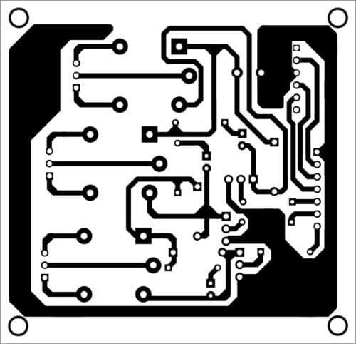
An actual-size PCB layout for the home automation system using Arduino Uno through Android app is shown in Fig. 4 and its components layout in Fig. 5. Assemble the components on the PCB as per the circuit diagram.
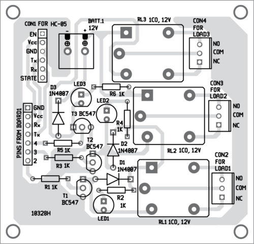
Download PCB and Component Layout PDFs: Click here
Then, connect the power supply to Arduino Uno either through its USB cable or 12V battery. Also, connect 12V power to all three relays, as shown in the circuit diagram.
Upload Arduino source code (HomeAutomation.ino) to Arduino Uno. The source code can be downloaded by scanning the QR code given in Fig. 6.
Next, pair Bluetooth module HC-05 with Bluetooth of your smartphone.
Download Android app (HomeAutomation.apk) using the QR code given in Fig. 7.
Install it on your Android smartphone. Next, open the app and pair Bluetooth module HC-05 with the Bluetooth of your smartphone. You will get the app on your phone as shown in Fig. 8.
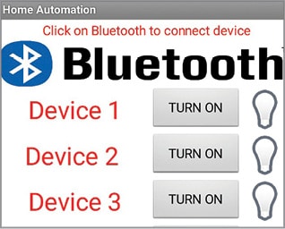
Now you may click on the buttons to control the appliances.
Download Source Folder
Kartik Gudali is an electronics enthusiast and RC hobbyist. Currently, he is working on the development of Android, Arduino, Raspberry Pi and Amazon Alexa.
Dileep Swamy is an electronics hobbyist and ham radio operator.


Hi,
Need Home Automation Using Arduino Through Android Device for home (all area), how to connect, we need business-level
use Node Mcu
no source folder. can you gave my a good link please?
The source folder is available at the end of the article.
tried the “Q” code, as I in USA, Google states violates terms of service.
I would also like the Source code and not the complied code, if possible
code for home automation
The source code is present at the end of the video.