


 This project is designed to control up to four home electrical devices using Node-RED, Raspberry Pi and local Wi-Fi network. Node-RED is a flow-based development tool for visual programming.
Node-RED
Node-RED is a graphical user interface (GUI)-based programming platform. It is a powerful platform to make Internet of Things (IoT) applications just by connecting its predefined code blocks like input, output, social media, Raspberry Pi GPIO and so on. You just need to connect predefined code blocks, called nodes, to perform a task. Connected nodes are collectively called flow.
Node-RED was developed as an open source project at IBM in 2013 to connect their hardware with Web-based applications, email servers, social media, etc. It has now become a popular IoT programming tool. When combined with Raspberry Pi, Node-RED becomes even more efficient for interacting with the physical world.

Preparing Raspberry Pi for Node-RED
The latest Raspbian operating system (OS) for Raspberry Pi comes with Node-RED application by default. If you want to install the latest version of Node-RED, run the following commands on the terminal:
sudo apt-get update
sudo apt-get upgrade
This will install the latest Node-RED on Raspberry Pi. If you are facing problems, install it manually by entering the following script on the terminal:
bash <(curl -sL https://raw.
githubusercontent.com/node-red/
raspbian-deb-package/master/resources/
update-nodejs-and-nodered)
Note that, after using this script to upgrade Node-RED, you will not be able to upgrade it again using apt-get upgrade command.
To open Node-RED from the desktop of Raspberry Pi, click on Raspberry Pi icon and then from the drop-down menu select ProgrammingNode-RED. Alternatively, you can type the following command on the terminal:
node-red-start //(to start Node-RED)
node-red-stop //(to stop Node-RED)
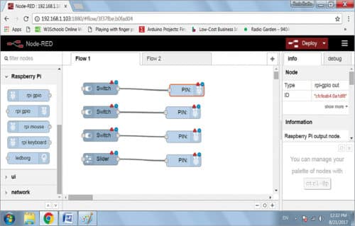
Node-RED console window will open, as shown in Fig. 1.
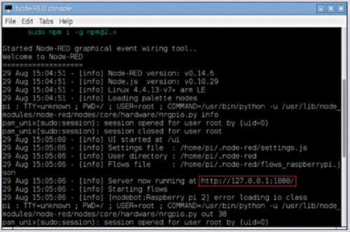
In case you do not know the IP address of your Raspberry Pi, type ipconfig in terminal window to check the IP address. Default port used in Node-RED for communication is 1880.
To open Node-RED graphical application, open the Web browser on Raspberry Pi and type the IP address of your Raspberry Pi as https://192.168.1.103:1880
You will get Node-RED graphical homepage, as shown in Fig. 2.
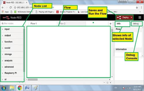
There are various coloured blocks on the left side. By scrolling down, you will see many nodes grouped together by categories including input, output, function, social, Raspberry Pi, UI and so on. You can use these nodes in your project by dragging and dropping them in the work area sheet at the centre. Different nodes are used for different operations.
GPIO and UI nodes may be missing in some older Node-RED versions. In that case, download these from the Internet by entering the following commands:
cd ~/.node-red
npm install node-red-contrib-gpio
npm install node-red-contrib-ui
Stop and restart Node-RED. You will get the updated nodes. (In some cases, rebooting the system may be required.)
Designing of home automation
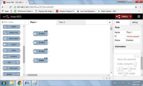
The above application will be used to control four household loads/appliances such as fan, TV, tubelight and LED dimmer through a cellphone. To do this, let us start with Node-RED UI node. We have a total of four loads—three switches and a slider—for four different loads. Drag and drop the switch and slider nodes from the node list. Do this four times for four different loads.
Note that, electrical loads will be controlled through UI switches and relays, as shown in the main circuit (Fig. 9). Relays are connected to GPIO pins of Raspberry Pi. Drag and drop four pins in the UI for Raspberry Pi GPIO nodes. Arrange these in the UI, as shown in Fig. 4.
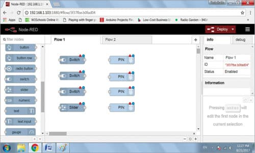
Make connections between the switches and pins to complete the flow. In switch node, there is a grey bubble on the right. Right-click on it and drag the cursor to the corresponding pin (GPIO) of Raspberry Pi, as shown in Fig. 5. Repeat the process for the other two switch nodes. For LED dimmer application, drag and drop the slider from UI node list and connect it to a pin of Raspberry Pi.
Configuring the nodes
Now, we need to configure the nodes according to hardware connections (Fig. 9). Use two tabs info and debug on the right of the window shown in Fig. 2 to know more about each node. Click on the node and all details about it will be displayed under info. Debug tab is used to monitor the function of the flow.
Deploy button is used as Run, which is used to start the flow.
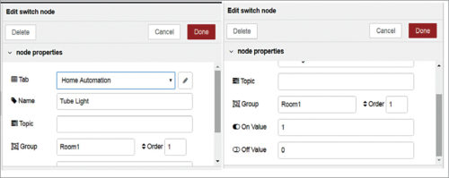
To configure the node, double-click on it. An empty window will open. Make the following changes (also shown in Fig. 6):
In node properties window, change the following:
Name: Tube Light, Group: Room1,
On Value: 1, Off Value: 0
Press Done to save the changes.


Do the same for other switch nodes with different names, as shown in Fig. 8.
To configure pin node, double-click on it from the window shown in Fig. 5.
In rpi gpio properties window (Fig. 7), make the following changes:
Pin: Select the GPIO pin you are using, Type: Digital output, check Initialize pin state and
select Initial level of pin – low (0). This will define all the pins initially low (off).
Name: GPIO_xx (which is you are using)
Press Done to save changes.
Do the same for the other two switches, except the slider. Input of the relay driver and LED dimmer circuit should be connected with GPIO pins of Raspberry Pi board, as configured in Node-RED flow. For the slider, define output type as PWM.
Final configured nodes are shown in Fig. 8.
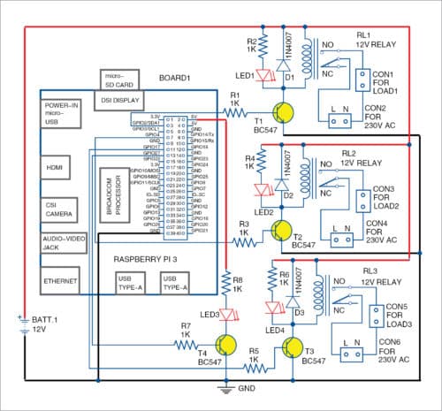
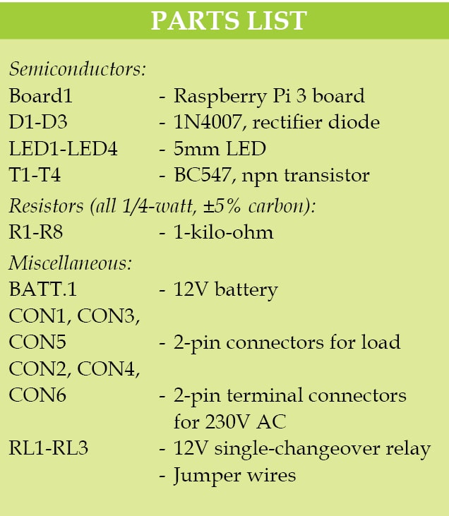
The circuit diagram of the home automation system is shown in Fig. 9. It is built around Raspberry Pi, 12V battery, 12V single-changeover relay and a few other components. Raspberry Pi 3 Model B+ board with Raspbian OS was used during testing at EFY Lab.
A PCB layout of the home automation system is shown in Fig. 10 and its components layout in Fig. 11. Assemble the components on the PCB as per the circuit diagram.

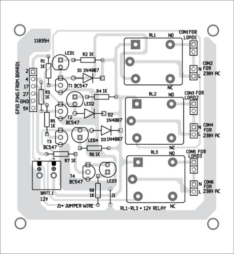
Download PCB and component layout PDFs: click here
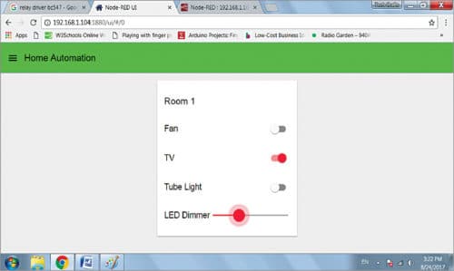
Testing Node-RED UI
After designing the flow diagram and making circuit connections, open the browser in any device from the same local network where Raspberry Pi is connected. Type the IP address of your Raspberry Pi as given below (this is as per this case; yours will be different), followed by pressing Enter:
192.168.1.104:1880/ui
The final UI screen will appear as shown in Fig. 12. You will see three slide switches and a slider. Using the switches, you can turn on or turn off the loads. The slider is used to control the light intensity of the LED connected to GPIO pin of Raspberry Pi.
When you operate the switch on the UI, corresponding GPIO pin of Raspberry Pi becomes high. Logic high signal at the base of the transistor makes it to conduct, current flows through it and the corresponding relay is energised. This turns on the corresponding electrical load.
GPIO pin of Raspberry Pi connected with transistor T4 is configured as PWM output. Slider in Node-RED UI makes the variation in PWM pulses. Pulses are fed to the base of T4 that drives a white LED. Pull the slider up and down using a mouse. You will see variations in PWM signal at its base, and light intensity of the LED will vary, accordingly.
Jayvardhan Pandit is working as an IoT-based product developer and PCB designer at Germanium Instruments Pvt Ltd, Bhopal

How to learn basics of home automation and which language is to learn