


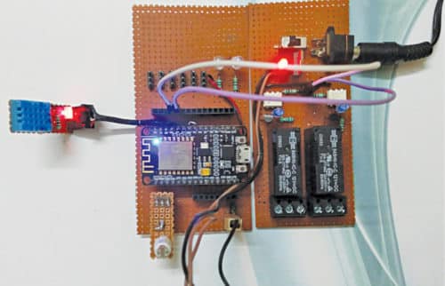
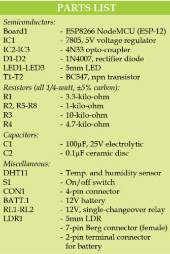
 This home automation system can measure temperature, relative humidity, light intensity and control two electrical equipment on Cayenne IoT (Internet of Things) platform. The two electrical equipment can be a light bulb and a ceiling fan, or any other electrical devices. The author’s prototype is shown in Fig. 1.
Basic IoT components
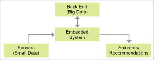
An IoT system has some basic components, as shown in Fig. 2, such as sensors, actuators, embedded system, network link, user interface and Big Data storage.
Sensors
In this project, two sensors are used. One is a light-dependent resistor (LDR) to sense ambient light intensity, and the other is DHT11 temperature and relative humidity sensor.

Actuators
Relays connected to output pins are used as actuators here. Electrical loads like lights and fans are connected to contacts of the relays, which are controlled remotely through a Web interface or mobile app.
Embedded system
Wi-Fi module ESP8266 (NodeMCU) used here is an embedded controller that is programmed through Arduino, to handle analogue or digital data received from sensors and to transmit over the Internet. At the same time, it accepts commands from the Web and accordingly actuates connected devices or actuators.
Network link
The Internet works as a network link to connect the embedded system to the outer world.
User interface
Cayenne platform supports Message Queue Telemetry Transport (MQTT) protocol for communication. MQTT protocol is a lightweight messaging protocol for use over TCP/IP protocol. It is designed for low-power devices that work on low bandwidth.
Cayenne platform has a simple drag-and-drop feature to create a dashboard in a few minutes. This saves time and effort for programming the user interface.
Big Data
This is also managed by Cayenne platform. Big Data is basically huge data that is collected from all connected devices, where type of data varies from device to device and data flow is at a very high speed. For example, Facebook gets more than 600TB of data daily from different posts (image or video), text messages, likes and so on.
Circuit and working
The circuit diagram of ESP8266-based home automation system is shown in Fig. 3. It is built around NodeMCU (ESP8266), an LDR, DHT11 sensor, opto-coupler 4N33 (IC2 to IC3), two relays (RL1 and RL2) and a few other components.
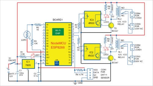
The circuit has two input channels—analogue input to measure light intensity through LDR1 and digital input to read values of temperature and relative humidity through DHT11. For measuring a wider range of temperature and humidity, replace DHT11 with DHT22 and then replace DHT11 with DHT22 in the source code.
The table shows the basic comparison between DHT11 and DHT22. The remaining specs, including pin configuration, are the same.
The circuit is powered by 12V DC supply, as it needs to drive 12V relays. 5V output is derived from 7805 regulator from the 12V input to power ESP8266 NodeMCU module.
NodeMCU V1.0 (ESP8266 ESP-12) has 11 GPIO pins and one ADC input pin with 10-bit resolution. Fig. 4 shows the pin details of NodeMCU module. It has 3.3V inbuilt voltage regulator and CP2102-based USB-to-serial converter that gives an easy interface with the PC for loading Arduino code to NodeMCU.
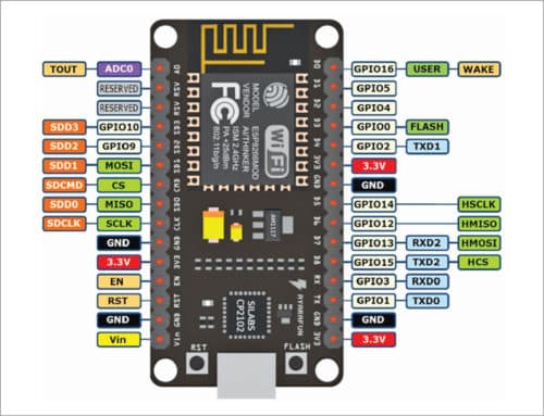
NodeMCU has a 30-pin (2×15) male header. Components around it are wired on a general-purpose PCB or on the designed PCB layout.
The LDR (LDR1) is used to sense the intensity of light around it, which is displayed as percentage on Cayenne dashboard. This is connected to A0 pin of NodeMCU module to read analogue voltage generated based on ambient light.
DHT11 sensor is used to read ambient temperature and relative humidity through digital I/O pin D5 (GPIO14). This sensor can split the data for temperature and relative humidity, and send it one at a time through the same output pin.
Two 12V relays are driven by two BC547 transistors through MCT2E/4N33 opto-isolators. Each relay can drive AC/DC load through the terminal headers connected to it.
Software
The software (ESP8266_HA.ino) is written in Arduino programming language, which allows writing the code within a few lines. The program makes the device communicate with Cayenne platform when connected to the Internet through an access point or Wi-Fi router.
To add board for ESP8266 in Arduino IDE, go to File Preferences and paste the link in Additional Board Manager URLs.
Open Boards Manager from Tools ®Board menu and install esp8266 platform. (Do not forget to select your ESP8266 board from Tools®Board menu after installation.)
For programming NodeMCU module, three unique identities are required from Cayenne website, namely, MQTT user name, MQTT password and Client ID. When the device is connected to the network, these IDs help Cayenne website to find the device and start communicating with it.
Other IDs required are your Wi-Fi SSID and password, if any, to connect with the local Wi-Fi network.
Before compiling and loading the code to NodeMCU module, install the following libraries in Arduino IDE as described below.
Cayenne-MQTT-ESP8266 library
This allows NodeMCU to communicate with devices on Cayenne platform.
DHT library
This allows DHT11 sensor to communicate with NodeMCU. Search Unified under Library Manager and install Adafruit Unified Sensor.
To add the above two libraries to Arduino IDE, go to Sketch®Include Library®Add .ZIP Library… Locate and install the files.
Alternatively, you can directly download and copy these libraries to Arduino/library folder of Arduino IDE. Download the libraries from these links: Link 1 and Link 2.
Construction and testing
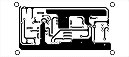
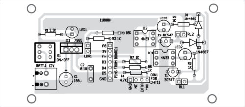
An PCB layout for ESP8266-based home automation system is shown in Fig. 5 and its components layout in Fig. 6. Assemble the components on the PCB as per circuit diagram. CON2-CON5 are not shown in the PCB (can be connected externally).
Download PCB and Component Layout PDFs: Click Here
Building dashboard on Cayenne IoT platform
Open website and create an account through Sign Up Free button on the top-right. Click on Bring Your Own Thing. The next page will give three unique strings: MQTT Username, MQTT Password and Client ID.
Copy these strings and paste in appropriate fields in Arduino code (ESP8266_HA.ino). Then, load the code in NodeMCU module through a USB cable. Wait for some time on this page to connect with the device on the network.
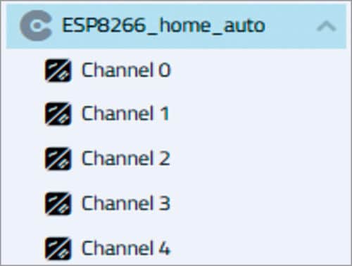
Once the module is connected to Wi-Fi, the Web page will move to the next screen. Here, your device will be given a unique name, which can be changed through Settings on the top-right. You will get a screen as shown in Fig. 7.
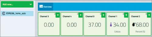
Click on plus (+) sign on each channel icon to add the channel to your dashboard. You will get the names of added channels on the left under Add New page as shown in Fig. 8.
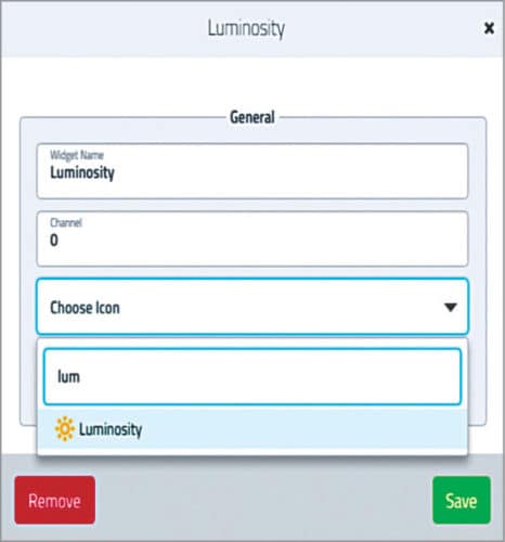
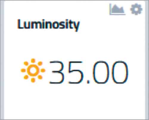
Click on Settings of Channel 0 and change its Widget name to, say, Luminosity. Click on Choose Icon, select Luminosity and click on Save. The icon will change as shown in Fig. 10. This will show the light around LDR in percentage.
Similarly, change the name of Channel 1 as Temperature and Channel 2 as Humidity. Make the required settings as mentioned in Channel 0. Now, proceed to channels 3 and 4 for configuring the buttons for controlling the two relays. Go to Settings of channels 3 and 4 and delete these using Remove button.
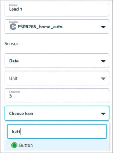
Now, click on Add New Device Widget. Select Custom Widgets® Button. Fill the required data for load 1 as shown in Fig. 11. Click on Add Widget. Similarly, repeat the load settings for Channel 4.
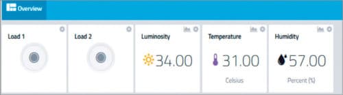
The final dashboard is shown in Fig. 12. Now, you are ready to control the two relays attached to channels 3 and 4. You can also monitor luminosity, temperature and humidity level of a place where your devices are located.
Download Cayenne app from Google Play Store, and login using the same credentials to start controlling the above-mentioned parameters from anywhere over the Internet.
Download source folder: Click here
Dayanand Sharma has over 18 years of experience in IT industry, and is currently working in a Noida-based MNC. His interests include embedded electronics, robotics and upcoming technologies


Dear sir
Update Data sent to mail
Not sure if opto-isolator is serving it’s purpose in the circuit diagram.
is it possible to use fire alarm with this same integration