During the ironing of clothes, they can get burnt, if the iron is kept over a cloth unattended. This usually happens when you get a phone call while ironing or get distracted by some other activity. To overcome this issue, we designed a smart iron box that automatically controls the iron wirelessly through a detachable motion sensor.

During ironing, the accelerometer and gyroscope sensor used in the project detects the motion and position (vertical or horizontal) of the iron and sends the information to the wireless control unit. The iron is switched on only when it is in motion and is in its normal horizontal position for ironing. Otherwise, it is kept switched off through the wireless control unit.
Proof of Concept Video Tutorial In English:
Proof of Concept Video Tutorial In Hindi:
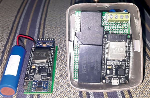
The project has a transmitting and a receiving section. The bill of material for the transmitter and receiver sections are shown in Table 1 and Table 2, respectively. Fig. 1 shows the author’s prototype with the transmitting device on the left and the receiving device on the right.
| Table 1: Bill of Material for Transmitter | ||
| Quantity | Item/Model | Description |
| 1 | TP4056 (MOD1) | TP4056 on a breakout board |
| 1 | Battery cell | 18650 3.7V lithium-ion rechargeable battery |
| 1 | SW_SPST (SW1) | Switch for input power |
| 1 | ESP32 DEVKITC-32D (MOD2) | ESP32 development board |
| 1 | MPU6050 (MOD3) | MPU6050 3-axis gyroscope and accelerometer |
| Table 2: Bill of Material for Receiver | ||
| Quantity | Item | Description |
| 2 | Screw_terminal_01x02 | Screw terminal block for input and output |
| 1 | AC to DC 5V power | 5V AC to DC power |
| 2 | 1N4007 (D1) | General-purpose diode |
| 1 | 1k (R1) | ¼W through-hole resistor |
| 1 | BC547 (T1) | NPN transistor |
| 1 | ESP32 DEVKITC-32D (MOD1) | ESP32 development board |
| 1 | RAYEX-L90 (RL1) | 30A T-type relay |
Smart Iron Box – Block Diagram
This project has a sensing part and a triggering part. The sensing part is the transmitter and the triggering part is the receiver. Fig. 2 and Fig. 3 show block diagrams of the transmitter and receiver, respectively.
Transmitter Block Diagram
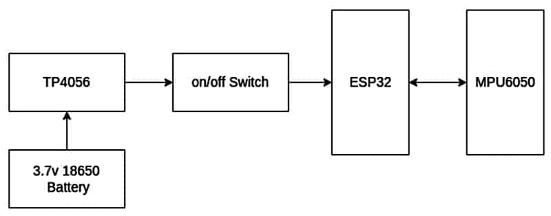
The transmitter uses MPU6050 as the sensor to detect the iron’s movement; it can detect movement in the x-axis, y-axis, as well as z-axis. This sensor is I2C compatible; the data it acquires is processed by the ESP32 microcontroller. The ESP32 processes the data and sends it to the receiver using the ESP-NOW protocol. The transmitter uses a 3.7V lithium-ion rechargeable battery, which is charged through a TP4056 charging module that is connected to a 5V USB charger.
Receiver Block Diagram

The receiver receives the command, if the command is valid (either 0 or 1), and triggers the relay. The ESP32 microcontroller transceiver is used for getting valid commands and triggering the relay. The receiver uses a 230V AC to 5V DC converter and a 5V relay module to switch the iron on or off. Whenever a valid command is received, ESP32 triggers a ‘high’ or ‘low’ signal to the GPIO pins connected to the relay, which switches the iron on/off.
Smart Ironing Device – Circuit Diagram
Transmitter Circuit Diagram
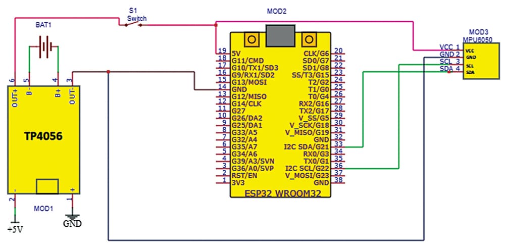
The circuit diagram of the sensing part (transmitter) is shown in Fig. 4. The transmitter is built around TP4056 (MOD1), ESP32 (MOD2), and MPU6050 (MOD3).
Receiver Circuit Diagram
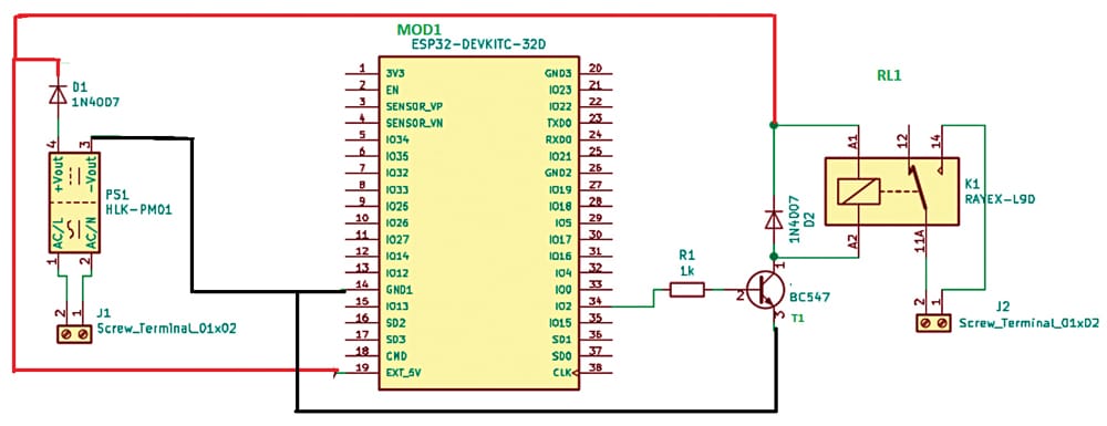
The circuit diagram of the triggering part (receiver) is shown in Fig. 5. The receiver is built around ESP32 DEVKITC-32D (MOD1), AC to DC 5V power source (PS1), and 5V single-changeover relay.
Also Check: Smart Switch for Electric Iron
ESP-NOW Wireless Communication Protocol
As the project has two parts, we need a protocol for communication between them. The ESP-NOW wireless communication protocol used for the purpose enables direct, quick, and low-power control of smart devices, without the need for a router. It helps in communication without any internet connectivity.
In its one-way communication mode, the protocol lets one ESP32 board send data to another ESP32 board (see Fig. 6). This configuration is easy to implement and great for sending data like sensor readings or on/off commands to control GPIOs from one board to the other. One ESP32 board can also send the same or different commands to different ESP32 boards. This configuration is ideal to build something like a remote control.
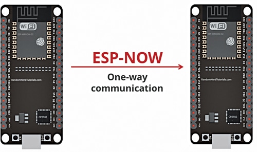
To communicate via ESP-NOW, you need to know the Mac address of the ESP32 receiver. Each ESP32 has a unique Mac address, which helps us identify each board for sending data to it using ESP-NOW.
Programming Smart Iron Box
Separate software codes are needed for the transmitter and the receiver, which are created using Arduino IDE. So, first, install the IDE and then install the ESP board. Then open and install the Addafruit mpu6050 and ESP-NOW libraries. Select the board as ESP32 and prepare the code for the transmitter.
Here the MPU 6050 6-axis gyro sensor and accelerometer are used to sense the motion of your hand ironing the clothes and get to know whether you are using the iron or not.
The working code’s flow chart is shown in Fig. 7. First, the device establishes the connection to the receiver using ESP-NOW and then it senses the motion and gives the signal to the receiver to turn the iron on or off.
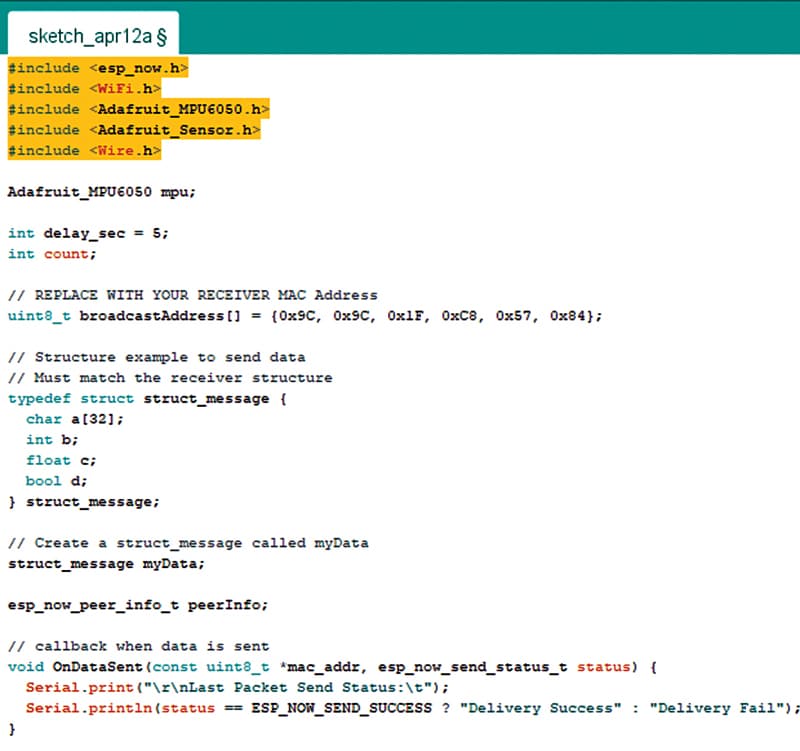
So, in the code, first, you need to initialize the ESP-NOW library and then the Addafruit mpu6050 library. Next, you need to configure the Mac address to the receiver to pair and communicate with.
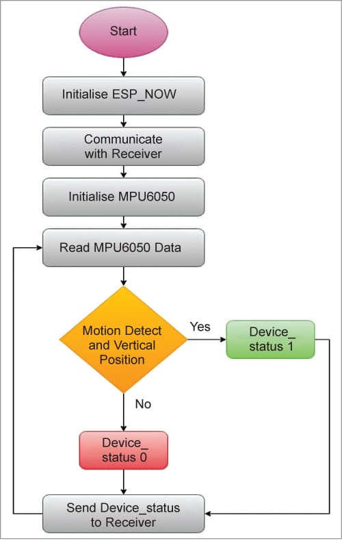
Fig. 8 shows the snippet of the source code of the transmitter. The loop function in the code checks the motion and sends a signal to the receiver. After completing the code, upload it after selecting the port name and board in IDE.
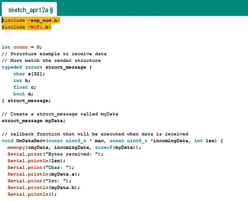
To prepare the code for the receiver, first, initialize the ESP-NOW library and then check the incoming message. In the loop, turn the relay pin on or off based on the message received. See Fig. 9 for the snippet of the source code of the receiver.
Upload the source codes of the transmitter and receiver into the ESP32 module. Place both transmitter and receiver inside the switch box, as shown in the author’s prototype in Fig. 1, and mount them on the iron. The final prototype, after proper installation of the controller box on the iron, is shown in Fig. 10.
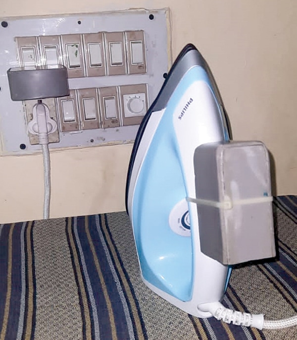
Now, even if you forget the electric iron on the cloth, it will not cause any harm; the iron will switch off automatically when not in use.
Download Source Code
The author S. Maheshwaran, an electronics researcher, completed MSc in electronics from St. Joseph’s College, Tiruchirappalli, Tamil Nadu. His fields of interest are human-centric automation systems, embedded systems, and robotics
The author K. Vairamani is also an electronics researcher. He did MSc in electronics from St. Joseph’s College, Tiruchirappalli, Tamil Nadu, and Ph.D. in instrumentation from Madurai Kamaraj University, Madurai, Tamil Nadu. His fields of interest are wireless sensor networks and human-centric automation systems


Sir, what is the power consumption of the smart Iron? How to calculate the Ampere rating of the relay contact?
Smart Switch Box For Electric Iron
https://www.electronicsforu.com/electronics-projects/hardware-diy/smart-switch-box-electric-iron
if you placed your iron motionless horizaontally for few seconds, what’s the chances that the cloth will not burn. Suppose your iron is at its peak temprature, by leaving it motionless the temprature didn’t fall immedietly. Please answer this, I am working on this project and I need to clear my doubts.