 Presented here is the Hydropower Generation circuit that generates power from a water pipe in a building using a microturbine. The generated electricity can be used to charge batteries, which can be used for emergency lighting or other such purposes.
Overhead water tanks are placed on the terrace of the house and filled from the underground sump or borewell using an electric pump for domestic use.
Water has high kinetic energy when it flows from a high to low level. Electricity can be generated using this kinetic energy with the help of a suitable microturbine. Based on the amount of water flow in the pipe, the power generated using the turbine can be varied.
Circuit Overview
The circuit diagram for hydropower generation from a water pipe is shown in Fig. 1. It is built around six rectifier diodes 1N4007 (D1 through D6), DC-to-DC regulator LM2596 (IC1), Schottky diode 1N5822 (D7), inductor (L1), micro hydro-turbine (MHT) and a few other components.
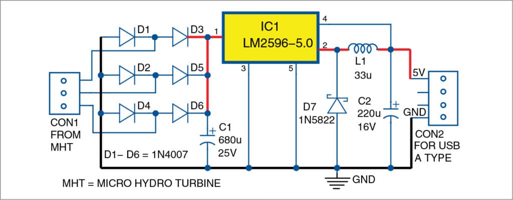
The circuit is built around DC-to-DC step-down switching regulator IC LM2596. The three-phase outputs (RYB) of MHT are connected to CON1. The image of MHT used in this project is shown in Fig. 2.

Bridge rectifiers (comprising diodes D1 through D6) convert AC output from MHT to DC voltage. IC1, L1 and D7 perform the step-down operation that converts high voltage to 5V DC. Capacitor C1 smoothens the rectified DC voltage, and C2 acts as a buffer for the output.
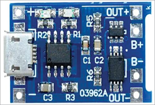
5V DC available at connector CON2 can be used to charge the single 18650 lithium-ion cells using the TP4056 module shown in Fig. 3. An emergency light or some other gadgets can be powered by a single lithium-ion cell.
About the Components
LM2596
LM2596 series of regulators are monolithic ICs that provide all active functions for a step-down (buck) switching regulator, which is capable of driving a 3A load with excellent line and load regulation. These devices are available in fixed output voltages of 3.3V, 5V, 12V and an adjustable output version. For example, LM2596-5.0 gives 5V fixed output.
LM2596 series offers a high-efficiency replacement for the popular three-terminal linear regulators. It substantially reduces the size of the heat-sink, and in some cases, no heat-sink is required.
Requiring a minimum number of external components, this regulator is simple to use and includes fault protection and a fixed-frequency oscillator. LM2596 is the upgraded version of IC LM2576, which has 52kHz switching frequency. LM2596 has a 150kHz switching frequency that offers usage of low-value capacitors and filters.
Micro Hydro-Turbine (MHT)
A generic MHT generator is used in this project. It has a maximum output voltage of about 20V, three-phase AC, maximum output current of about 150mA with a flow rate of about 2.5 to 25 liters per minute.
Assembly and Testing
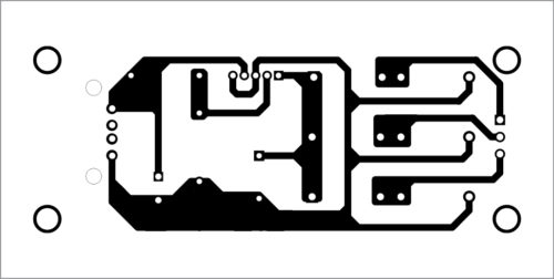
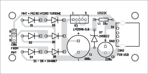
A PCB layout for hydropower generation from a water pipe is shown in Fig. 4 and its components layout in Fig. 5. Assemble the circuit on the designed PCB. Connect MHT RYB outputs across CON1 using external wires. The power supply for the circuit is provided by MHT.
Download PCB and Component Layout PFDs: click here
After assembling the circuit on the PCB, fix MHT with a suitably sized water pipe—size of the water pipe depends on the coupling heads of MHT. When water starts flowing through the pipe continuously, you should be able to get 5V DC across CON2.
Improving Efficiency in Microturbine Power Generation
- Flow-Rate Monitoring: Install a sensor to monitor water flow rate, which could improve energy output and battery charging efficiency.
- Power Management: Include a power management module that directs power to critical devices based on battery level and available flow.
- Overvoltage Protection: Include overvoltage protection to protect the circuit in the event of unexpected increases in water flow rate that surpass the regulator’s input range.
- Battery Overcharge protective: Incorporate a protective circuit to prevent battery overcharging, assuring durability and safety.
A. Samiuddhin is B.Tech in electrical and electronics engineering. His interests include LED lighting, power electronics, microcontrollers and Arduino programming
This project was first published on 13 November 2019 and recently updated in November 2024.


Excellent idea. Where to buy this type MHT?
Hi . I thank you very much for this very good and powerful electronic site that has provided excellent, complete and perfect projects to everybody. I tried to find this good site on the internet to enhance my electronic knowledge. I am in a very small town designing all electronic circuits on copper fiber by hand. I couldn’t fully find the projects I needed in my home country and now I have reached my goal through your good site. Thanks a lot to everyone who has contributed valuable content on this site. Do not be tired
Thank you for your feedback.
Thank you for your valuable feedback.
This micro turbine hardly generates say 6 to 12 vdc based onthe flow and current just 10 to 20ma maximum
basically this is water flow sensor. better to use any 12 vvdc motors you will get atleast 200 to 500 ma
Thank you for taking interest to my article. The micro turbine used in this project generates AC, not DC. The output of the micro turbine is 20V, 150mA maximum depends upon the water flow. Any micro turbine which has the maximum output upto 40V, 3A can be used in this project. Make sure that the micro turbine doesn’t have internal regulator. If so, the efficiency will be compromised.
I would like to ask how to change the AC power generated with 3 phase AC to DC and then this DC to line frequency (the frequency through which power is supplied to houses) AC?
Your query is not directly related to this project. Anyway you need inverter circuit for that.
Hello sir,I search the MIcro Hydro Turbine in Amazon and Flipkart but I couldn’t find a 20 V Output but only 12V output is available ,so will it still work?
And one more Question,I also search for heat sink of LM5496 but it is not available ,so will any heat sink work?
Only 12v MHT is available in amazon and Flipkart, will its still work ?
Sir 20 V MHT is not available in the shop nor in Amazon or in Flipkart but 12v MHT is available so will it still work?
How to get that PCB can you please tell me?
Hi Jeeva, we have included a download link for the same within the article. Please check.
Instead of LM5496 kindly suggest which heat sink we will use?
LM5496 is not used in the project.I think you referring to LM2596, its heat sink is easily available on various online stores
do you have video tutorial?
Hello sir, I am actually working on this idea as my graduation project and I am quite stuck with the calculation side , we have purchased the MHT , water flow meter , and the pressure sensor yet, we are not getting the calculations right . We have installed these equotments on a pipe we have a valve to control the power flow and we have everything settled yet when we are measuring the volt the digital multimeter is obtaining 1.3 microvolt and no current is detected . We have the Arduino board we have installed the program on desktop to obtain measures regarding the pressure and water flow , also with no output . Our deadline is due in 30th of December and we are literally stuck. Can you please provide us with any help , tip? Anything would be appreciated at this point .
My email is [email protected] I would appreciate you getting in touch with us .
Thanks in advance .
Dear Jude,
You can refer article “Digital Flow Meter For Water Pipes” Electronic for you August -22 issue. Alternatively you can refer https://www.electronicsforu.com/electronics-projects/digital-water-flow-meter