


 Presented here is a 4-digit Industrial Digital thermometer based on ATmega16 microcontroller (MCU), which can measure temperature up to 1024°C.
Normal thermometers have a limited range, and can easily get damaged at very high temperatures. So thermocouples are used in industries for measuring very high temperatures. This circuit uses a K-type thermocouple along with MAX6675 IC for temperature readings.
MAX6675 IC has inbuilt cold-junction compensation (that is, zero temperature reference) and it digitises the signal from a K-type thermocouple. It converts the signal to digital (binary) with an accuracy of 0.25°C. Temperature is displayed on four 7-segment displays (common-anode) without decimal point.

The basic principle of a thermocouple is that, if two junctions are exposed to two different temperatures, an emf is generated between the two junctions of two dissimilar metal wires. K-type thermocouples can measure temperatures up to 1300°C, and are widely used in industries for measuring temperatures of furnaces, heaters and the like.
Circuit and working
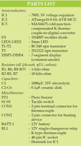
The circuit diagram of the industrial digital thermometer is shown in Fig. 1. It comprises ATmega16 MCU (IC2), MAX6675 converter (IC3), 5V voltage regulator 7805 (IC1), four 7-segment displays (DISP1-DISP4) and a few other components.

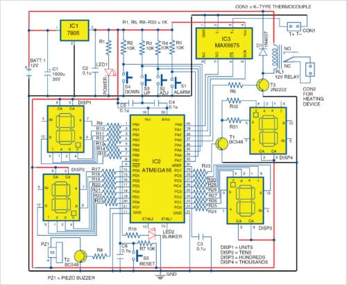
The circuit generates an alarm through a buzzer, and a relay gets energised on crossing a pre-determined temperature value. Thus, this circuit regulates the heating device by switching it on or off through the relay. The heat source is connected between COM and NC pins of the relay.
You can also connect a draught fan between COM and NO pins of the relay. In normal operation, the relay will control the main relay (that is, high current capacity/hold-back relay), which controls the fuel or other inputs to the furnace/heater.
Software
The firmware code (MAX6675thermo-meter.c) is written in C and compiled using AVR Studio. The hex code generated is burnt into ATmega16 using a suitable AVR programmer board.
Initially, when the circuit is switched on, the program makes all four displays glow as a self-test. Then, the displays show an alarm temperature value for a while. Thereafter, the temperature is displayed continuously. While MAX6675 module is capturing temperature value, LED2 blinks continuously.
The circuit identifies open-loop condition through the displays. If thermocouple is not properly connected to MAX6675, OPE will be displayed. If there is an error with MAX6675 module, Err will be displayed.
Download Source Code
Construction and testing
A PCB layout of the industrial digital thermometer is shown in Fig. 2 and its components layout in Fig. 3. After assembling the circuit on the PCB, connect a 12V battery across BATT.1.
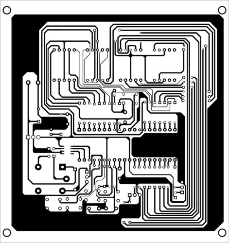
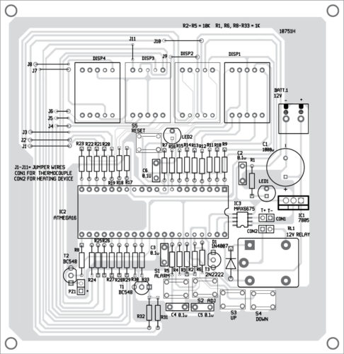
Download PCB and Component Layout PDFs: Click here
To change the alarm or current temperature value, press switch S1 (alarm) or S2 (adj), respectively. If all four displays (DISP1 through DISP4) start blinking and LED2 stops blinking, it indicates that the system is in edit mode.
Now, press S3 for value increments and S4 for decrements. Alarm value will change in steps of 10 units and temperature in steps of one unit. If there is no button pressed for more than 10 seconds, the current displayed value will be saved to EEPROM of the MCU, and the system will exit edit mode and display the current temperature value.
During testing of the circuit, note the following:
1. Polarities of K-type thermocouple should be matched with MAX6675 polarity markings (T+ and T-).
2. MCU board and MAX6675 should be kept at a distance from the heating zone.
3. Accuracy of temperature and response time of change of temperature are mostly dependent on the thermocouple.
4. MAX6675 is more accurate up to 700°C (refer data sheet).
5. Press switch S5 momentarily to reset, if there is a problem with the display.
With this project, you can adjust the accuracy of temperature readings to ±25°C with respect to a calibrated thermocouple.
Download source folder: Click here
Fayaz Hassan is manager at Visakhapatnam Steel Plant, Andhra Pradesh. He is interested in MCU projects, mechatronics and robotics

The link on this page to Download PCB and Component Layout PDFs file links to the wrong file. The PCB images in the downloaded file appear to be for a simple motor control circuit, not the Industrial Digital Thermostat described in the article.
Any chance of getting the proper PCB files?
Thanks,
David M
Thank You David, we have updated the article with original links.
hello,
PCB Size?
how can we get code,can you send link??
The source code is present at the end of the article.
Sorry but when we try to download PCB file and source code it says site is unavailable. Please contact hosting. Please help me out.
Hi Vinay, we are facing some technical issues with the source page. We are working on rectifying the error.
i am waiting for your reply.
You can download now.
Dear Sirs,
the download link for the PCB and Component Layout PDFs is incorrect.
Please can you fix this?
Kind Regards
Mitsos
Please refresh the page and retry.
Dear Sirs,
the download link for the PCB and Component Layout PDFs is incorrect.
The downloaded file Industrial-Digital-Thermometer.zip (37889 bytes) contains the code files of this project.
Please can you fix this?
Kind Regards
Mitsos
Please refresh the page and download.