When I first thought about making a voltmeter, I wanted something small, easy to carry, and quick to use. I imagined it as a tool I could keep in my toolbox or use as part of a quick diagnostic kit.
The goal was to create a tool that could measure voltages in two ranges (0-3.3V and 0-24V) and connect to Wi-Fi to display the readings in real time on a webpage.
I wanted it to be no bigger than the palm of my hand and have the flexibility to switch between the two voltage ranges through a web interface.
The solution? IndusVoltmeter – a voltmeter designed around the IndusBoard Coin, which houses the ESP32-S2 chip. The design offers portability, simplicity, and remote connectivity, all wrapped up in a compact package.
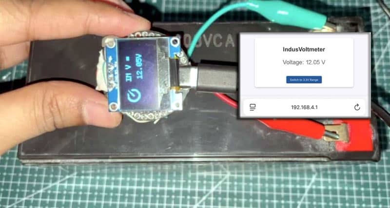
Here’s how I designed and built it.
Table of Contents
In today’s fast-paced world, having a small, portable, and convenient tool is essential for quick troubleshooting and projects. Whether I’m working in the lab, on-site, or at a client’s place, the ability to carry a voltmeter that doesn’t take up much space is a must.
The compact design, about 3 cm in size, ensures it’s easily portable without compromising functionality. And with Wi-Fi connectivity, I can view the measurements remotely, without needing to be physically close to the device.
Bill of Material

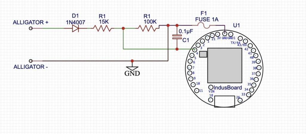
IndusVoltmeter Circuit Design
Step 1: Choosing the Voltage Measurement Ranges
The design of the IndusVoltmeter revolves around two voltage ranges:
- 0-3.3V: This range is for low voltage measurements where we directly read the voltage via the ESP32-S2’s ADC pin. The ESP32 has a 12-bit ADC that can read voltages in this range without any modification.
- 0-24V: This range requires a voltage divider circuit to scale down the voltage. The voltage divider uses two resistors to safely scale high voltages (up to 24V) to the ADC pin, which can only handle a maximum of 3.3V.
Step 2: Creating the Voltage Divider
To measure voltages in the range of 0-24V, I needed to use a voltage divider to bring down the input voltage to a level that the ESP32-S2 could safely read. The voltage divider consists of two resistors:
- R1 = 100kΩ
- R2 = 15kΩ


These resistor values scale a 24V input down to approximately 3.3V, which is safe for the ESP32’s ADC pin to read.
Step 3: Adding Protection for the Circuit
To ensure that the circuit lasts a long time, I added protection components:
- Reverse Polarity Protection: A 1N4007 diode was placed in series with the power supply. This ensures that the diode will prevent damage to the board if the power is connected incorrectly.
- Overcurrent Protection: I added a 1A fuse to protect against excessive current, which could otherwise damage components.
- Noise Reduction: To prevent fluctuating readings caused by electrical noise, I used a 0.1µF capacitor between the ADC pin and GND to stabilize the signal and improve the accuracy of voltage readings.
Step 4. Adding the OLED Display (Optional)
Since I wanted the voltmeter to work with a web interface and also show the voltage on a physical screen, I decided to add an OLED display. This display will show the voltage in real time and help me quickly check the readings without having to access the web interface.
But you can skip this if you don’t want it. It still works and shows on the phone display when connected to the device.
I used a 128×64 OLED connected via I2C (SDA, SCL) to the IndusBoard Coin. The display is connected to pins 8 and 9, which are the default I2 pins for the IndusBoard. Check the pinouts of the Indusboard Coin.
Coding IoT-Based Smallest Wireless Voltmeter
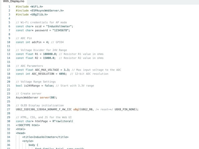
We’ll need to install a few libraries using the Arduino IDE’s library manager. First, install the following libraries:
Now, let’s include these libraries in our code:
#include <WiFi.h>: This library is used to connect the ESP32-S2 to Wi-Fi in AP (Access Point) mode.#include <ESPAsyncWebServer.h>: This library creates an asynchronous web server for serving HTML and handling client requests.#include <U8g2lib.h>: This library is for controlling the OLED display and rendering text.
Global Variables
- Wi-Fi Credentials: These are the SSID (network name) and password we’ll use to connect the ESP32-S2 to Wi-Fi in AP mode.
- ADC Pin: The ADC input pin (GPIO4 in this case) is defined as `adcPin`.
- Voltage Divider: We’ll use two resistors (R1 and R2) to scale down the voltage from the 24V range to a safe level.
- ADC Parameters: We’ll set the maximum ADC voltage (3.3V) and ADC resolution (4096, for 12-bit ADC).
- Voltage Range: We’ll use a boolean flag (`is24VRange`) to indicate whether the voltmeter is in the 24V range.
Web Server
- HTML, CSS, and JS for the Web UI: The HTML structure defines a simple UI with a voltage display and a toggle button to switch between the 3.3V and 24V ranges. CSS is used to style the page, and JavaScript manages the toggling of the voltage range and periodically fetches the voltage data from the server.
Setup Function
- Serial Setup: We’ll initialize the serial communication for debugging purposes.
- ADC Configuration: This setting sets the ADC resolution to 12 bits (4096 levels) and configures the ADC attenuation to 11 dB. This means you can read voltages up to 3.3V.
- Wi-Fi AP Mode: The ESP32-S2 startsAs an access point with the SSID “IndusVoThe IP address of the AP is printed for client connection.
- OLED Initialization: Initializes the OLED display to show voltage readings.
- Web Server Routes:
- Root Route (“/“): Serves the HTML page with the voltage display and toggle button.
- Voltage Route (“/voltage”): Reads the analog voltage from the ADC pin, scales it to the appropriate range (either 3.3V or 24V), and sends the result as JSON.
- Set Range Route (“/setrange”): Allows the user to toggle between the 3.3V and 24V voltage ranges. It reads the “range” parameter from the URL and sets the is24VRange flag accordingly.
Loop Function
- Voltage Measurement: The analogRead(adcPin) reads the analog value from the ADC pin. The raw ADC value is then converted into a voltage based on the ADC resolution and the range selected.
- OLED Display: The measured voltage is shown on the OLED display using the u8g2 library. The voltage is updated every second.
- Font and Display Setup: Text is drawn on the OLED display with a specific font size. The voltage value is updated in real time, and the screen is refreshed every second.
HTML, CSS, and JavaScript
- The webpage displays the current voltage and allows the user to toggle between the 3.3V and 24V ranges.
- JavaScript fetches the current voltage from the /voltage endpoint every second and updates the display.
- The toggle button sends a request to the /setrange endpoint to change the voltage range when clicked, and it updates the button text based on the new range.
Testing IndusVoltmeter
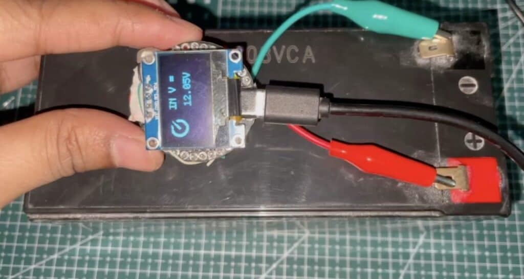
Now, after uploading the code, if you wish to use the device to measure the voltage range below 0 V and 3.3 V without the circuit, you can directly connect the positive voltage source (+) to pin 4 and the negative voltage source (-) to the negative I2 GND of the device.
Please note that you should cross-check the polarity connections and ensure they are correct to avoid short circuits, as reverse polarity protection is not included in this circuit. You can use the circuit diagram to add a polarity protection layer and a fuse for short-circuit protection.
If you want to monitor the voltage continuously, you can connect the laptop to the Indusvoltmeter’s Wi-Fi SSID (password: 1234567890) and search for the IP address 192.168.4.1 in the browser. This will display the voltage readings on the laptop.
For measuring voltages above 24 V, ranging from 0.0 V to 24 V DC, you can create the circuit as described above and connect the ADC to the power source and ground.
Then, connect the device to the hotspot of the device and the laptop using the password set in the code.
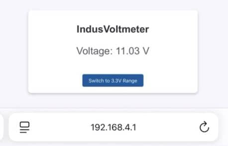
In the browser, access the webpage of the device using the IP address 192.168.4.1. You can then switch to the 24 V range using the toggle button on the webpage.


