


 A special feature of this infrared burglar alarm is latching operation. Also, the circuit is highly sensitive.
The circuit comprises transmitter and receiver sections. Whenever IR beam between the transmitter and the receiver is interrupted, the alarm circuit is triggered and the buzzer sounds continuously. It can be reset only by pressing the reset button.
Infrared burglar alarm circuit
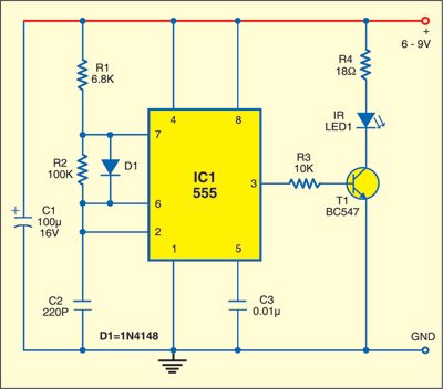
The transmitter section is built around IC 555 (IC1), which is wired as an astable multivibrator and produces about 38kHz frequency. IR LED1 emits 38kHz modulated signals up to a distance of 4.6 metres (15 feet).

Circuit operation
The modulated IR beam from the transmitter continuously falls on the receiver section built around IR sensor TSOP1738, IC CD4011 and some discrete components. The receiver sensor TSOP1738 responds to 38kHz frequency. The modulated IR beam falling on receiver sensor TSOP1738 makes its output low and when somebody crosses the path of IR rays it senses this and its output goes high momentarily, which triggers the flip-flop.
The flip-flop circuit uses IC CD4011. Two NAND gates of IC2 are used here. Input pins 2 and 13 of IC2 are normally held high. When the IR beam falls on TSOP1738, the output of IC2 remains low. The alarm circuit de-activates due to cut-off condition of transistor T2 and the buzzer remains silent.

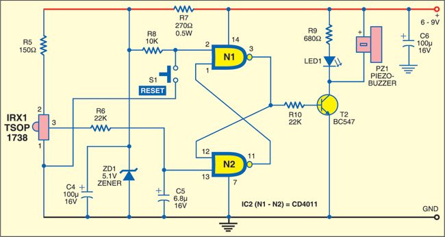
The IR transmitter and receiver units are mounted opposite to each other on the sides of entry door or gate. When the invisible beam between the transmitter and receiver is interrupted by anybody passing through, the output of the receiver goes low for a moment and triggers the flip-flop. Output pin 3 of IC2 goes high and latches at that position. The alarm circuit activates due to conduction of transistor T2 and the buzzer sounds until the receiver circuit is reset through switch S1.
Assemble the transmitter and receiver on separate, matchbox-size PCBs. For alarm purpose, use a piezobuzzer having internal oscillator.
The circuit works off 6 to 9V DC. Even unregulated supply can be used. After connecting the power supply, the alarm may trigger. Press reset switch to make the circuit ready for detecting burglars.
Feel interested? Check out other electronics projects.

why was the first circuit is removed?
The 1st circuit was not removed, we have shifted our website from ASP to word press.
thank you, was it working?
Sir, can I use CD4093 instead of CD4011?
i have made the circuit but buzzer remains on no matter what i do
The receiver can’t do what it is supposed to do IMHO:
The TSOP1738 output goes high when the IR beam is interrupted and this does not trigger the flipflop since it needs a change from high to low to be triggered.
The solution is simple: the CD4011 contains two other gates. One of them can be used to invert the output from the TSOP1738 so that interruption of the IR beam leads to a change from high to low on pin 13 of CD4011.
The receiver circuit cannot do what it is supposed to do : when the IR beam is interrupted the ouput of TSOP1738 goes from low to high. This can not trigger the flip-flop, since it needs a change from high to low.
The solution is to invert the output of TSOP1738 using one of the other gates of the CD4011
BUZZER REMAINS PERMANENTLY OFF NO MATTER TRANSMITTER IS TRANSMITTING OR NOT. WHEN RESET SWITCH IS PRESSED ONCE, BUZZER GETS TURNED ON NOW WHEN TRANSMITTER STARTS TO TRANSMIT BUZZER GETS TURNED OFF BUT WHEN IR SIGNAL IS INTERRUPTED THEN BUZZER REMAINS TURNED OFF.
REMARK:- HERE INSTEAD OF CD4011 IC I AM USING HCF4011 IC.
can I get the full set of component along with PC board for and instruction guide
The circuit built there is continuous buzzer on, what may be the problem, I have used PCB mountable buzzer and the sensor is TSOP 8138, as TSOP mentioned in circuit is obsolete
When I power the Receiver Cct even with out connecting the trans cct the buzzer goes on .Kindly HELP.I have to Submit the project by mid Dec 19.
Regards
Ravi
Please send an email to [email protected].
Sir, In the Transmitter circuit what is the part number used for diode D1? What is the output dutycycle of the transmitter?
Dear Sir,
Diode D1 is 1N4148 and dutycycle of the transmitter is 50%
due to this diode.
Regards