


In this IoT LED Lamp project, we handle the output pin of ESP32 for switching and dimming a DC LED lamp using a local Web server. For a local Web server, we do not need an Internet connection; we can handle everything over Wi-Fi.
To make this IoT project work, we use additional circuitry, because LED being of high power cannot be directly controlled by ESP32.
Material needed to get started with IoT LED Lamp
1. ESP32 NodeMCU (Check the datasheet from the Internet, if you are using a different version.)


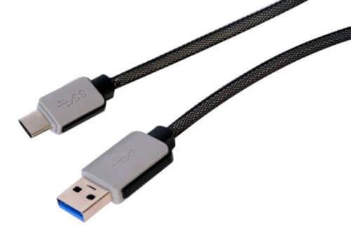
2. USB Type C cable to program ESP32 from a laptop or PC—most Android phones use this type of cable.
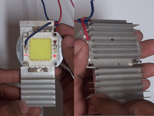
3. 20W 12V DC LED with heat-sink, which will act as the lamp to control over Wi-Fi.
4. NPN BD-139 transistor to control brightness or, technically, voltage supplied to LED. We will drive its base voltage through ESP32.
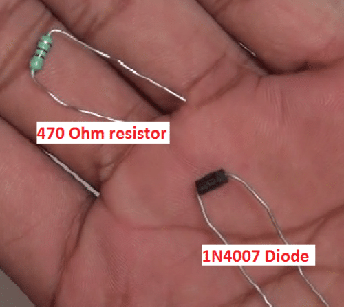
5. 470-ohm resistor for BD-139 base and IN4007 diode to protect the circuit from any reverse voltages from 12V supply.
6. Regulated 12V supply from a battery eliminator or a charger with 12V 1A rating.
7. Some wires and a breadboard.
Steps for software setup for setting up IoT LED Lamp
(Note: Ignore this step if you already have ESP32 board setup in Arduino IDE)
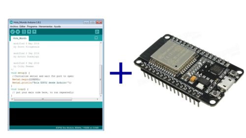
To code ESP32, we need an integrated development environment (IDE). We use Arduino IDE software. Arduino IDE is a cross-platform application, written in Java and coded in C/C++ with some special rules. Download the latest Arduino IDE from here.
Arduino IDE does not contain support for the ESP32 family. To install ESP32 Board in Arduino IDE, refer here.
Connection and wiring
Follow these connections to setup the circuit.
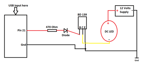
In the circuit, we drive the base voltage of BD139 using ESP32 pin 21. Base voltage controls the flow of potential between collector and emitter of BD139. This is an application of a transistor in an amplifying region. Now, we can control voltage and, hence, the brightness of an LED.
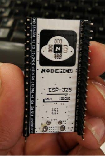
Remember to check the ESP32 datasheet. General-purpose input-output (GPIO) pin numbers are mentioned on its back.
Power ESP32 using 5V supply (current not more than 500mA), or directly plug it in with the help of a USB or powerbank. LED will be powered depending on its need—some are 12V, whereas others are 5V (current<=1A).
Note: All grounds must be common.
The code
Download the code from the link given below, and open it in Arduino IDE.
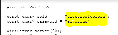
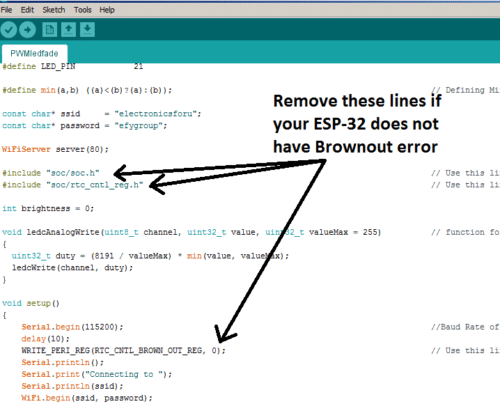
Before uploading, you need to make some changes in the code. Edit Wi-Fi name and password here, within double-quotes.
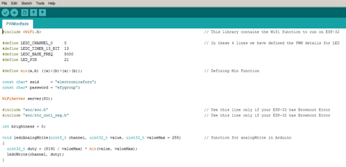
These three lines can be removed if the ESP board does not have any Brownout error.
In the code, #include, helps Arduino IDE to run the functions of ESP32. This library contains all Wi-fi.xxxx functions used in the code.
Unfortunately, ESPs still do not have an analogWrite function. So, we will have to create one. Here, we made ledcAnalogWrite and defined the values that will be used in that function.
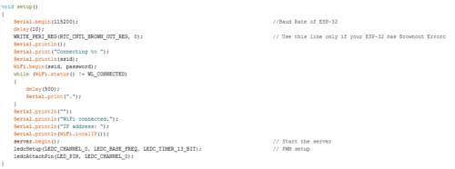
In void setup(){}, perform all setups needed for running the main program, like baud rate in Serial.begin(), Wi-Fi initialisations, pin mode setup, brightness function setup and start the server from Server.begin().
In void loop(), we have our main program.
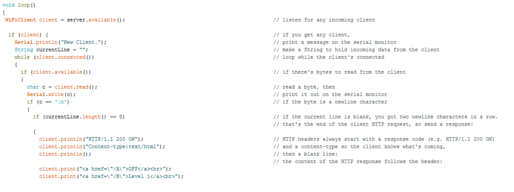
Our aim is to first create a Web Page on the server and then attach it with various buttons. To create this Web page, we need HTML code embedded in Arduino Code like this.
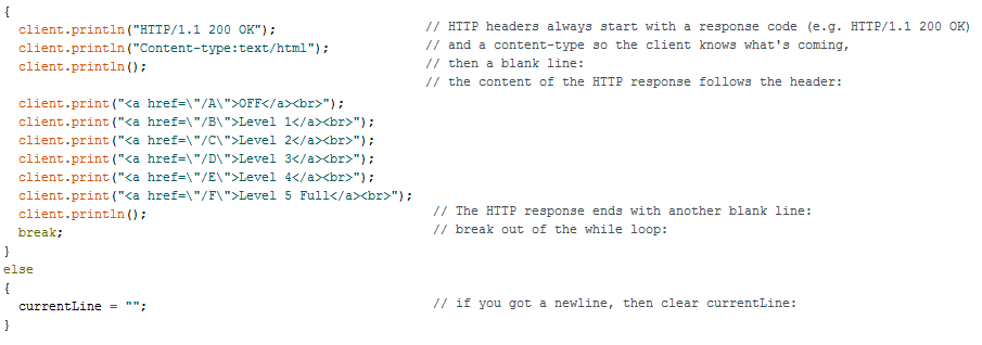
This will hit some buttons on the Web page, which can be redirected to set the brightness of the DC LED.
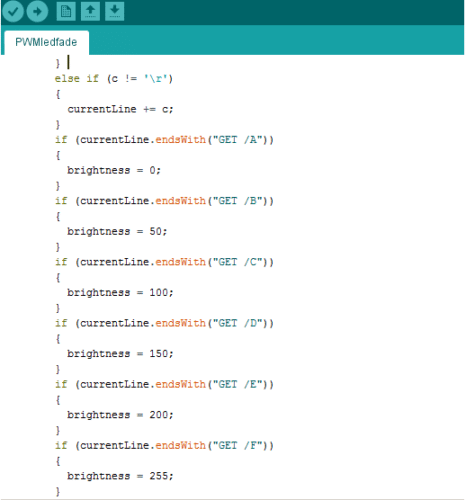
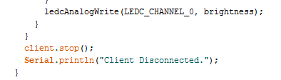
After value for brightness is set, we can write these values in analogWrite function we created for ESP32.
Save the code.
Now, go to Tools>Boards Manager>ESP32 Dev Module. Then, go to Tools>Upload Speed>115200. Select your COM port.
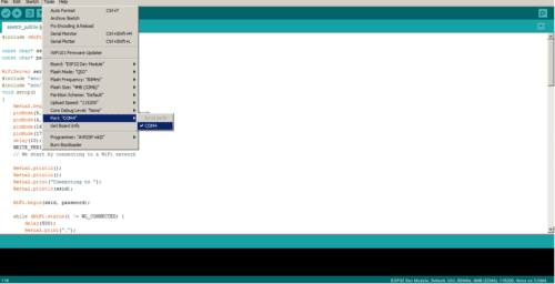
Upload the code, and power up everything.
Connecting the Webserver
After uploading the code, go to Open Tools>Serial Monitor. ESP32 will try to connect to Wi-Fi and display its IP address on Arduino serial monitor.
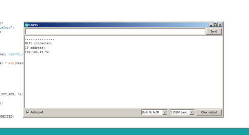
Make sure that the Wi-Fi router to be connected is already open. Hit this IP address in the browser of the device connected to the same Wi-Fi.
Url: http://192.168.xx.xx (your IP displayed in Arduino serial monitor)
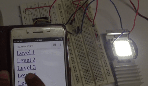
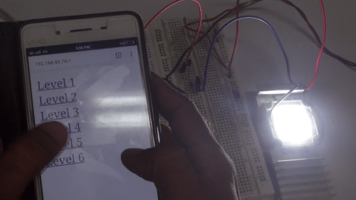
You will be able to see the HTML Web page mentioned in the code.
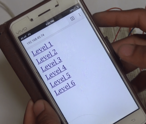
Control dimming through these levels seen on the Web page.
Check the similar Lamp project.
how to change a simple webpage this layer into android application