


 This IR-based light control circuit turns on the lights at the portico, car parking or other areas when a motorbike or car enters through the gate to cross the sensing area. It can also be used as an electronic watchdog for your house, by activating an alarm simultaneously.
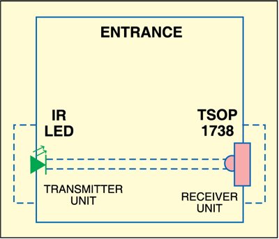
The system consists of a transmitter-receiver pair along with a switching circuit. The transmitter and the receiver are mounted face to face on the opposite pillars of the gate such that the IR (infrared) beam produced by the transmitter falls directly on the IR sensor of the receiver. The system gets activated when someone passes through the gate to interrupt the IR beam falling on the sensor.
IR-based Light Control Circuit
Transmitter
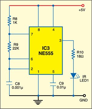
Fig. 1 shows the transmitter circuit. It consists of an infrared (IR) LED and a NE555 timer (IC3), which is wired as an astable multivibrator producing a frequency of around 38 kHz. The 38kHz infrared beam is transmitted through IR LED1.

Receiver
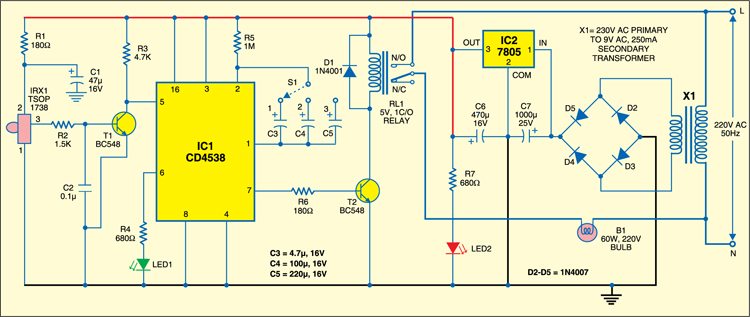
Fig. 2 shows the receiver circuit. It consists of IR sensor TSOP1738, dual monostable multivibrator CD4538 (IC1) and a few discrete components.
When the IR beam falls on the sensor, its output pin 3 remains low and transistor T1 conducts to make pin 5 of IC1 high.

When anyone interrupts the IR beam falling on the sensor, its output pin 3 goes high to trigger IC1 (at pin 5) through transistor T1. As a result, output pin 7 of IC1 goes high for the preset time period. Transistor BC548 (T2) conducts to energise relay RL1 and LED1 is switched off. When the monostable time period is over, LED1 glows again.
The time period of IC1 can be increased or decreased by selecting a proper value for the capacitor connected between pins 1 and 2 of IC1. A three-position small rotary switch along with capacitors C3, C4 and C5 is used to select the time period of IC1.
Diode 1N4001 (D1) acts as a freewheeling diode. The bulb (B1) to be switched on and off is connected between the pole of relay RL1 and neutral terminal of AC mains. It connects to the live terminal of AC mains supply via normally-opened (N/O) contacts of the relay when the relay energises.
Regulated 5V power supply for the transmitter and receiver units is derived from AC mains through step-down transformer X1, bridge rectifier (consisting of diodes D2 through D5) and regulator IC 7805 (IC2).
Construction & testing
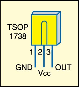
Assemble the transmitter and receiver circuits on two separate general purpose PCBs and enclose in suitable cabinets. Fig. 3 shows the pin configuration of sensor TSOP1738. Mount the transmitter and receiver units on the opposite pillars of the gate as shown in Fig. 4.
The article was first published in June 2010 and has recently been updated.


pcb layout please