 Usually light dependent resistors (LDR) and photodiodes are used as light sensors to activate or deactivate circuits based on the presence or absence of light. But a common transparent LED can also be used in the place of an LDR or a photodiode. Here is a simple circuit that uses a transparent red LED as the light sensor that switches on a white LED when the red LED is in dark.
Ordinary transparent LEDs function as light emitters and light detectors. These detect a narrow band of wavelengths of light and their p-n junction forward biases to generate around 1V voltage with a minute current of 0.030mA when exposed to bright sunlight. So a transparent LED can also be used as a light sensor like a photodiode.
LEDs detect a much narrower band of light having peak sensitivity at a wavelength slightly lower than the wavelength these emit. For example, a transparent red LED emits around 660nm light and responds better to orange light at 610nm.
Circuit and working
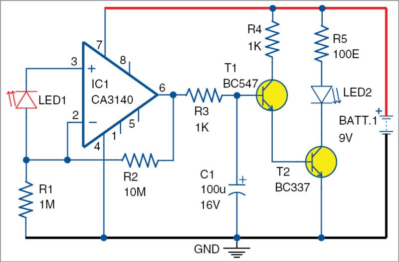
Circuit diagram of an LED as a light sensor is shown in Fig. 1. It is built around op-amp CA3140 (IC1), transistors BC547 (T1) and BC337 (T2).

The circuit uses high-gain CA3140 to amplify the feeble current generated by the LED in the presence of sunlight. CA3140 is a high-performance 4.5MHz BIMOS operational amplifier having MOSFET inputs and bipolar output.
Gate-protected MOSFET transistors in the input circuit provide very high input impedance, typically around 1.5-tera-ohm. These require very low input current (as low as 10-pico-ampere) to change their output status. So even without external bias, IC1 performs well. Here, transparent LED1 and its low current generated will bias IC1 when exposed to light.
In the circuit, transparent red LED1 is connected in reverse-bias mode with biasing resistor R1. IC1 is wired as a simple current-to-voltage converter. It is a trans-impedance amplifier with resistor R2 to set the current feedback. So when sunlight falls on LED1, it generates a minute reverse current that keeps the voltage at the inverting input of IC1 slightly higher. This keeps output of IC1 low. As a result, T1 and T2 remain off to turn off white LED2.
When LED1 is in dark, reverse current ceases and suddenly IC1 changes its output to high state. This turns on T1, followed by T2. The white LED2 connected to the collector of T2 turns on.

Construction and testing
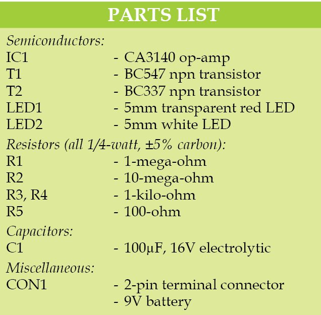
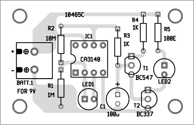
A single-side PCB layout for the circuit is shown in Fig. 2 and its component layout in Fig. 3. Assemble the circuit on the PCB and enclose in a suitable box.


Download PCB and component layout PDFs: click here
Light sensor LED1 should be a high, bright, transparent 5mm red LED. Transparent green and white LEDs also work well but red LEDs show more sensitivity towards ambient light. Light from white LED2 should not fall on red LED1 sensor. In place of the white LED, a relay can be used to switch on AC loads, so that the circuit functions as an automatic nightlight.
The circuit works off a 9V battery power supply.
This article is a part of the Top 10 LDR-based Electronics Projects. If you want to read more projects based on LDRs can go through this article.
D. Mohan Kumar was associate professor at Government College for Women, Thiruvananthapuram, Kerala


very good work
Thank you for your feedback.
Interesting! I never thought of using LED’s as light detectors rather than emitters.
To reduce cost, can IC 741 be used to replace CA3140 in this ?
can it be used for collge projects?
Yes, it can be used as a college mini project
Good to know, thank you for sharing.
What is the role of capacitor in this circuit?Bcos when I removed the capacitor from the circuit the output was same..
Here, capacitor C1 acts as energy storage device. With capacitor C1, white LED2 will glow for sometime even when the input is withdrawn. Whenever pin 6 of IC1 goes high, it started charging and at the same time, white LED2 will glow. When pin 6 goes low, C1 started discharging, and white LED2 will glow until C1 discharges completely. The circuit will work without C1 but that is not the main goal of the design.
This circuit is not working… I have tried many times from the above given circuit diagram… Where is the problem??
The circuit is fully verified by our team. Please recheck your circuit.
Why is this circuit not working??
Dear Gaurav, the circuit is fully verified by our team. Please recheck your connections.
Fake Circuit, not working practically.
Dear Rohit, the circuit is fully verified by our team. Please recheck your connections.
May be you’ve not given it a try or probably you messed up the construction
the system is not working.
The circuit is fully verified by our team. Please recheck your connections.
can you advise what would cause the output voltage that lights the white led to be the same as the actual battery voltage
Good circuit, sir can you tell me how or where to connect the relay. Its for my school project. Thanks. By the way Guys it is working please check you circuit and connections.
how do we get to know that feedback “R” would be of only mega ohms and the resistors before white led would be 1k. Or why bc547 and bc337 would be used and again why bc337 is connected to the other one why don’t we stay with single bc547….this is the circuit which I saw and build but what if something is hitting my mind and I want to build that without searching it on google how would I know that what specific comp. are to be used.
I think have wrong at LED1 It’s light sensor with revert arrow
Interesting that we can use LED as a light detector. My application is little different – I have a 12V cooling fan which I want to switch ON in the morning (to cool my solar charge controller) and switch OFF in the night (opposite to light a bulb in the night).
can you help me with the circuit – I will give this circuit to children as a project for the above application.
you can mail me directly. Thank you in advance.