


 Here is a simple circuit of a light-activated switch that automatically turns on the light/lamp at night and switches it off during the day. You do not have to manually operate the switch.
Circuit and working
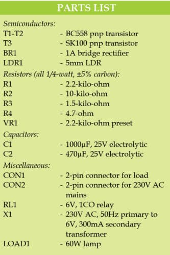
The circuit diagram of the light-activated switch is shown in Fig. 1. Base of pnp transistor T1 (BC558) is connected to 6V through a preset VR1 (2.2K), and to ground through resistor R1 (2.2K) and light-dependant resistor LDR1. Output of T1 is further connected to T2 (BC558) and power transistor T3 (SK100). Both emitters of T1 and T2 are connected to each other and then to 6V through R4 (4.7E). A 6-volt relay is connected between +6 Vcc and emitter of T3.
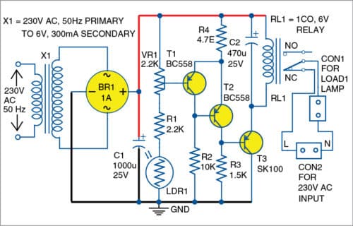
As light falls on LDR1, its resistance reduces. As a result, T1 conducts, T2 switches off and T3 conducts. This engergises relay RL1, and the lamp turns off. This is because, when RL1 is energised, the pole contact is towards NO contact. As darkness falls, resistance of LDR1 increases, and T1 and T3 stop conducting. This results in switching off RL1 and the lamp connected through relay NC contact turns on.

Power supply. A 6V DC voltage is required to power the circuit. A 230V primary to 6V, 300mA transformer X1 and a bridge rectifier IC are used to convert 230V AC to 6V DC power supply. Electrolytic capacitor C1 (1000µF/25V) is used to filter the voltage from the bridge rectifier output.
Construction and testing
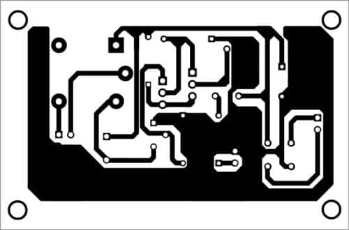
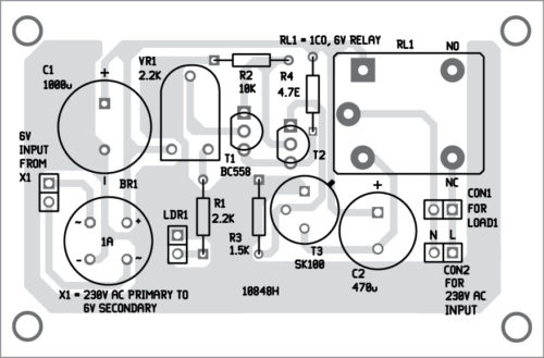
An actual-size PCB layout of the light-activated switch is shown in Fig. 2 and its components layout in Fig. 3.
Download PCB and component layout PDFs: click here
Solder all components on the PCB. A PCB-mount relay is used to solder on the PCB. A suitable heat-sink is recommended for T3.
After placing the components and soldering these, calibrate and adjust the circuit. Connect the 6-volt power supply to the circuit. Connect a lamp through CON1 connected across RL1. Face LDR1 towards sunlight. Take a small screwdriver and adjust the 2.2K preset (VR1) until RL1 turns on. Obstruct the light coming to LDR1 with your hand so that RL1 turns off. You can adjust VR1 to set the desired light source level.
Caution
Caution should be taken while operating the circuit on 230V AC mains.
Raj K. Gorkhali is a hobbyist and a regular contributor to EFY