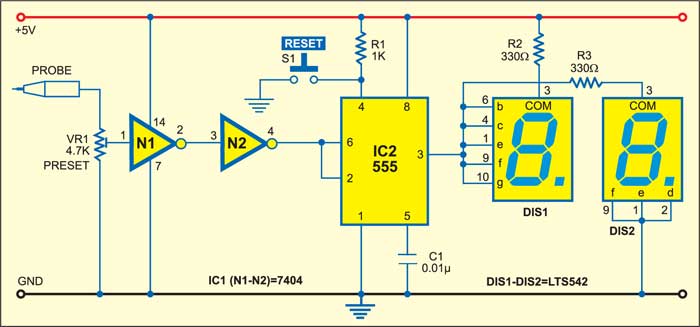
 This logic high/low indicator circuit comprises two ICs. One is hex inverter IC 7404 (IC1) and the other is a bistable multivibrator built around timer IC 555 (IC2). A logic probe is connected to the first inverter (N1) through potmeter VR1, while the output of the second inverter (N2) goes to the common point of trigger pin 2 and threshold pin 6 of IC2.
To operate the logic high/low indicator, the circuit is reset by momentarily pressing switch S1 and the logic probe is held either high or low.

The output of inverter N2 depends on the condition of the logic probe. If the input probe voltage is low (typically 0.2V, max. 0.4V), the output of N2 also remains low. Similarly, if the input probe voltage is high (typically 3.4V, max. 5V), the output of inverter gate N2 is also high. Tactile switch S1 is used for initial resetting of the bistable. Output pin 3 of bistable IC2 is connected to displays DIS1 and DIS2 that show ‘high’ (H) or ‘low’ (L) logic to indicate the input logic level.
When the logic probe is held at low position (ground), trigger pin 2 of the bistable goes below 1/3×5.0V=1.7V to make the output high. Display DIS1 shows ‘ L’ to indicate ‘low’ logic, while DIS2 remains ‘off.’
On the other hand, when the logic probe is held at ‘high’ logic state, trigger pin 2 of the bistable goes higher than 2/3×5.0V=3.3V and its output goes low. Display DIS2 shows ‘H’ to indicate ‘high’ logic, while DIS1 remains ‘off.’


