


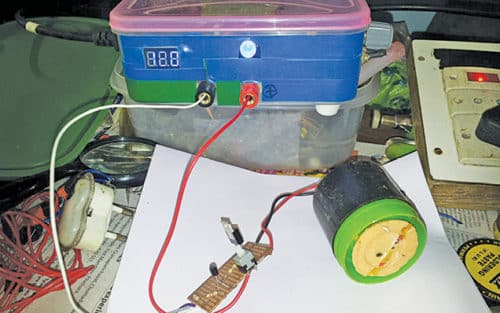
 Presented here is a loop-based anti-theft alarm circuit using a simple wire loop as sensor. It can be used to protect any device against theft, or as a door opening alarm. Make sure that when the device moves, or the door opens, the sensing loop breaks, too. The author’s prototype is shown in Fig. 1.
Circuit and working
The circuit diagram of the loop-based anti-theft alarm is shown in Fig. 2.
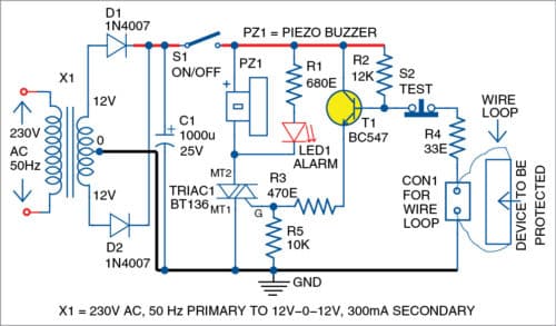
The circuit is built around a triac (BT136), transistor BC547 (T1), a piezo buzzer (PZ1), transformer (X1) and a few other components. Triac is used as the switching device. Transistor is used to drive the gate of triac.

Switch on the alarm circuit using switch S1. If the sensing loop is closed, base of transistor T1 is pulled down to ground. So T1 is reverse-biased and its emitter current is zero. That is, triac will be in off condition when loop is closed. Hence, the alarm will be off.
When an unauthorised person picks up a device under wire-loop protection, the loop breaks and it forward-biases T1. This is because its base is connected to the positive rail of the power supply through resistor R2. When T1 conducts, triac gets its gate current via resistor R3 (470-ohm).
When triac is on, LED1 glows and at the same time an alarm is sounded off through buzzer PZ1. Now, even if the loop is connected, the alarm cannot be stopped until the circuit is disabled using S1, which is hidden from view.
Power supply section consists of a centre-tapped transformer (X1), two diodes (D1 and D2) and a capacitor (C1). During testing, a centre-tapped transformer with 230V AC primary to 12V-0-12V, 300mA secondary was used in the circuit.
Construction and testing
A PCB layout of the loop-based anti-theft alarm is shown in Fig. 3 and its components layout in Fig. 4. Assemble the components on the PCB as per the circuit diagram. Enclose the circuit in a small box along with S1 and keep it hidden.
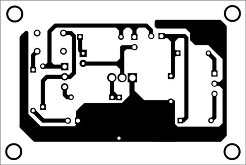

Download PCB and Component Layout PDFs: click here
Attach the wire loop to the device to be protected. Switch on the circuit. Switch S2 is optional for manually testing the circuit. After the wire loop is installed, when you press S2, the loop wire breaks, LED1 glows and an alarm sounds off. This verifies that the circuit is working fine.
P.V. Vinod Kumar is an electronics hobbyist