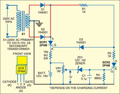
 Here is a very simple and low-cost battery charger for 12V, 7Ah lead-acid batteries. It can also be used for powering automobile engines and emergency lighting systems.
Low-Cost Battery Charger Circuit
As shown in the figure, diodes 1N4001 (D1) and 1N4001 (D2) form a full-wave rectifier. The rectified voltage appears across SCR1 and the battery to be charged. At low battery voltages, SCR2 is in cut-off state. SCR1 is triggered by the gate current flowing through resistor R1 and diode D3, and the battery charging starts.

At the start of charging, the reference voltage Vr of the battery is determined by a voltage-divider circuit. This voltage is too low to drive zener diode into conduction. Thus, the zener diode is effectively open and SCR2 is in cut-off state as the gate current is zero. Capacitor C1 prevents accidental triggering of SCR2 due to voltage transients in the circuit.
Circuit operation
As charging continues, the battery voltage rises to a level high enough to turn on the zener diode and trigger SCR2, which brings down the voltage to a level too low at the junction of R1-R2 and SCR1 cuts off. This occurs when the battery is fully charged and the open-circuit state of SCR1 cuts off the charging current. The regulator starts recharging the battery whenever the reference voltage Vr drops below the zener diode’s breakdown voltage and prevents overcharging when voltage Vr is equal to the breakdown voltage of zener diode ZD1.
The article was first published in March 2007 and has recently been updated.


Wat is meant by VR1(1M)
What is the value of VRI ( 1M)
VR1 is variable resistor with value of 1-mega-ohm
Can I add charge and full charge indication with scr 2p4mwhere and how to put
Can I use this on 12V 9Ah battery?