


 Solar streetlights can be easily integrated with a dusk-dawn controller by simply employing a pnp transistor and a few resistors where the solar panel itself works as the sensor. But what about other lighting sources that do not employ solar panels such as automatic lighting systems in small wind turbines, automatic lighting in cars or battery-based systems where automatic lighting is necessary?
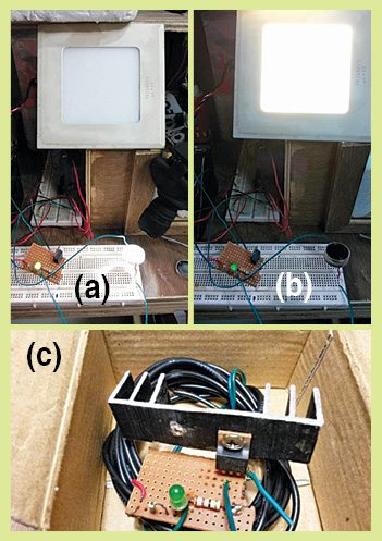
A simple, low-cost, yet an effective solution for the dusk-dawn controller circuit is described here. Author’s prototype is shown in Fig. 1.
Circuit and working
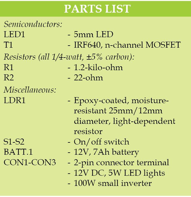
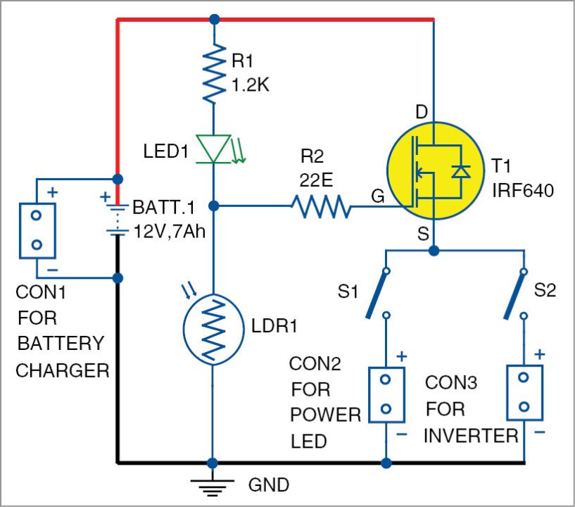
Circuit diagram of the dusk-dawn controller is shown in Fig. 2. It is built around a light-dependent resistor (LDR1), n-channel MOSFET IRF640 (T1), 12V LED light or a small inverter (100W) and a few other components.

The 12V battery-operated circuit is designed such that the common battery supply is used for operating the circuit as well as for load, that is, for power LED/small inverter circuit. Resistors R1 and R2 are used as a voltage divider and a current limiter in the circuit, respectively. LED1 is used as circuit de-activation indicator. LDR1 is the main component for actuation of the dusk-to-dawn sensing. The n-channel MOSFET IRF640 is for the switching action of the LED light or the small inverter connected to the system through switches S1 and S2, respectively.
 With daylight falling on LDR1 (dawn mode), resistance of LDR1 becomes low, a small current flows through LED1 and it glows. At the same time, due to low voltage across LDR1, MOSFET IRF640 does not trigger. So load (LED light/inverter) remains off.
But when the surrounding area of LDR1 (dusk mode) is dark (at night), resistance of LDR1 becomes very high, no current flows through LED1 and it does not glow. At the same time, due to higher voltage across LDR1, IRF640 triggers. So load light (power LED light/ inverter) comes on, provided switch S1 or S2 is on.
IRF640 can handle a maximum current of approximately 18A, but you can limit its application to approximately 8A-9A only, based on which the heat-sink is attached to the MOSFET.
Construction and testing
A single-side PCB for the dusk-dawn controller is shown in Fig. 3 and its component layout in Fig. 4.
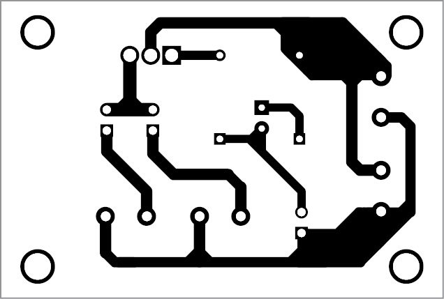
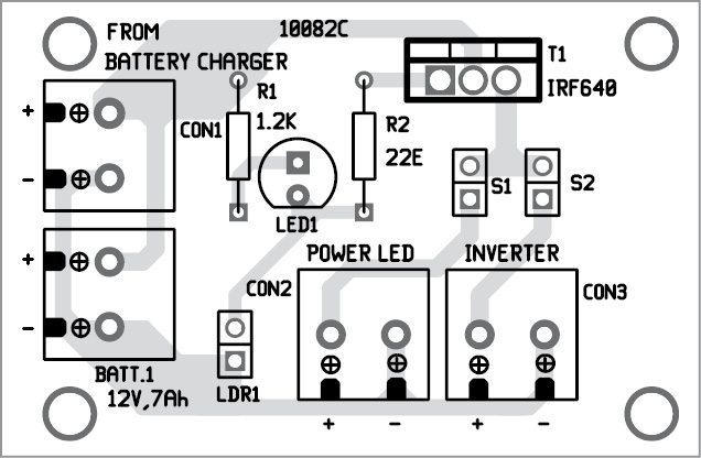
Download PCB and component layout PDFs: click here
After assembling the circuit, enclose it in a suitable box. The unit should be fixed on the pillar in such a way that the daylight falls directly on LDR1.
Bikash Rai is assistant engineer in Energy & Power Department, government of Sikkim. He is also a part-time research scholar at Sikkim Manipal Institute of Technology, Sikkim.
What is the use of the inverter in this circuit????
please I need the circuit diagram
Dear Amaal, the circuit is present on the second page.
If the indicator LED (LED1) is removed from the circuit will this reduce the battery drawdown but mor importantly will the circuit still work?