
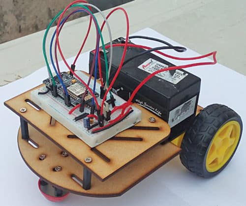
 There are many types of robots, from simple toy cars to advanced industrial robots. The Wi-Fi-controlled IoT robot described here uses NodeMCU and Blynk app. It can be controlled wirelessly using any Wi-Fi enabled Android smartphone. The prototype wired on the breadboard is shown in Fig. 1.
Circuit and working
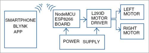
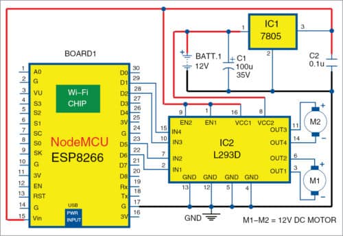
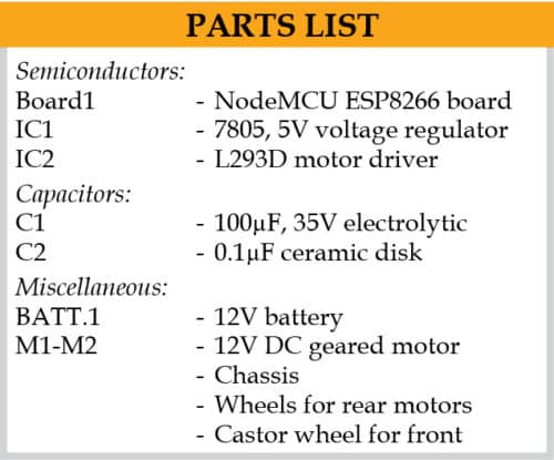
The block diagram of the low-cost Internet of Things (IoT) robot is shown in Fig. 2, and its circuit diagram is shown in Fig. 3. It is built around NodeMCU (board1), 5V regulator 7805 (IC1), motor driver (IC2), two DC motors (M1 and M2), 12V battery and a few other components.
The project programming of NodeMCU and interfacing Blynk app on Android device.

NodeMCU
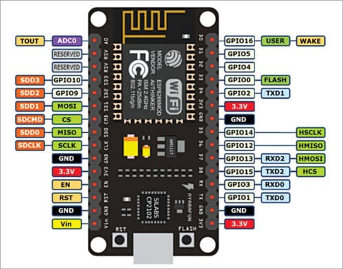
NodeMCU is the heart of this project. Pin details of NodeMCU module are shown in Fig. 4. It is a small board compatible with breadboards and has an ESP8266 Wi-Fi controller chip operating at 2.4GHz frequency. It has micro USB port for power, programming and debugging. It also has reset and flash buttons. It can be powered using 5V via micro USB port.
Blynk app
Blynk app is used for controlling the robot from anywhere in the world. It is designed for IoT applications for smart controllers using Arduino, NodeMCU and Raspberry Pi. Various sensors including temperature, humidity, pressure and accelerometer are supported by the app.

Blynk app is simple to use, flexible and has input/output features like gauge, slide bar, joystick, etc. It has less programming but requires specific Blynk header files for interfacing. Header files and libraries are easily available on GitHub.
By adding the library in Arduino IDE, you can compile the code and program NodeMCU easily.
The joystick in Blynk app is set between 0 and 255, which are the digital reference values. When the joystick moves up and down, digital values vary between 0 and 255. When it moves along horizontal axis, voltage at x pin changes. Similarly, when it moves along vertical axis, voltage at y pin changes.
Hence, there are four directions (-x, +x, -y and +y) of joystick outputs. When the joystick moves, voltage on each output pin goes high or low depending on direction. In neutral (central) position, the joystick shows both x and y values as 128 on Blynk app.
Blynk app development
The steps for running the setup are given below.
1. Download Blynk app from Play Store and install it on your smartphone.
2. Either login or signup. You can use your current Gmail account for this.
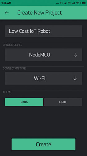
3. Give a name to your project, say, Low-Cost IoT Robot. Select NodeMCU board from Choose Device, and Wi-Fi in Connection Type to create a new project (Fig. 5).
4. An authentication token will be sent to your registered e-mail address. Note that down as you will need it in Arduino source code (Blynkrobo.ino) later.
5. Open Arduino IDE and add the required library from this link. Extract and paste it to libraries folder in Arduino.
6. Open Blynkrobo.ino code using Arduino IDE. Copy the authentication token sent to your e-mail and paste it in the code as shown in the following lines. Replace ssid and password with your Wi-Fi’s SSID and password.
char auth[]=“81ee172dab924b808f73c14be0e3f2aa”;
7. Connect NodeMCU with your PC/laptop using a USB cable. Under Tools, select NodeMCU 1.0 (ESP-12E Module) board and com port. Then compile and upload the source code to the board. After uploading the code, open serial monitor to check whether NodeMCU board is connected to Wi-Fi or not.
8. Go back to the created project in Blynk app. Select Joystick from Widget Box and click on Joystick to configure it (Fig. 6). Select V1 pin, and define x and y axis range from 0 to 255 (Fig. 7).


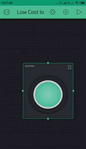
9. Press Play located at the top-right of the screen.
A graphical joystick panel in Blynk app will appear, as shown in Fig. 8. This panel provides digital outputs that keep changing according to the direction you move the joystick to, using your fingers. The joystick has two axes: x and y. Exact direction of the movement is interpreted through the microcontroller (NodeMCU) and the IoT (Blynk).
Software
Circuit operation is done using the software program loaded into the internal memory of NodeMCU. Arduino IDE 1.6.8 is used to compile and upload the program. Software Blynkrobo.ino is written in Arduino language, which allows writing a code within a few lines. The program makes the device communicate with Blynk IoT Application Platform when connected to the Internet through an access point or Wi-Fi router.
To add ESP8266 (NodeMCU) in Arduino IDE, select File→Preferences and paste this link.
Open Board Manager from Tools→Board Menu and install ESP8266 platform. (Note: Do not forget to select your ESP8266 board from ToolsBoard menu after installation.)
In this project, external header files are needed for programming. This is a simple way to detect the joystick, and compare x and y values from Blynk app using simple programming functions.
Construction and testing
Wire the IoT robot circuit on the breadboard along with NodeMCU. Connect the left and right motors on the chassis of the robot. Fix a suitable castor wheel at front of the chassis.
In this project four digital I/O pins (D1 and D2, D5 and D6) of NodeMCU are connected to inputs of L293D H-bridge motor driver IC for controlling right and left motors of the robot.
Case 1
When you move the joystick with your finger in x-negative direction on the joystick panel, digital value is less than 30. In this condition, voltage at digital pin D6 is high, and voltages at digital pins D5, D1 and D2 are low. In this condition, the robot moves in left direction till you release the button on joystick panel.
Case 2
When you move the joystick in x-positive direction, digital value is less than 220, and voltages at pins D6, D5 and D1 are low, while at pin D2 it is high. In this condition, the robot moves in right direction till you release the button on joystick panel.
Case 3
When you move the joystick in y-negative direction, digital value is less than 30, voltages at pins D6 and D2 are high, while at pins D5 and D1 are low. In this condition, the robot moves in reverse/backward direction till you release the button on joystick panel.
Case 4
When you move the joystick in y-positive direction, digital value is less than 220, voltages at pins D6 and D2 are low, while at pins D5 and D1 are high. In this condition, the robot moves in forward direction till you release the button on joystick panel.
Case 5
Joystick is in neutral condition. Digital values for x and y directions are 128. Here, voltages at all digital pins (D6, D5, D2 and D1) are low. In this condition, the robot is in stop condition.
For downloading the source code: click here
If you found this IoT project useful then you may also like Top 30+ IoT Projects | IoT Project Ideas for Enthusiasts.
Pamarthi Kanakaraja is assistant professor in ECE department, KL University, Vaddeswaram, Andhra Pradesh