


 This simple, low-cost night lamp automatically activates at night and deactivates in the daytime. It incorporates battery charging circuit with protection against over-charging and deep-discharge. The circuit comprises three sections, namely, power supply, over-/under-charging control and lamp control.
A low-cost night lamp circuit
The power supply section comprises regulator IC3 and IC4, bridge rectifier BR1 and transformer X1. The 230V AC mains is stepped down to 12V AC by transformer X1, rectified by bridge rectifier BR1 and filtered by capacitor C4. The rectifier output is regulated to 12V and 9V by regulators 7812 and 7809, respectively. 9V is used to charge the battery and power the lamp control circuit while 12V supply is used for relay RL1 operation.
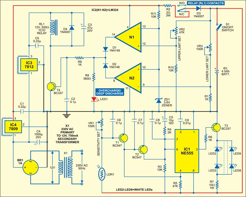
The over-/under-charging control section is built around IC2 and some discrete components.

Circuit operation
If the battery voltage is 5.5V to 6.5V and mains power is available, the relay remains de-energised. In this condition, the battery charges through the normally-closed (N/C) contacts of relay RL1.
Now when the battery voltage goes below 5.5V, the voltage at its inverting pin 9 goes below 3.6V. As a result, the output of op-amp N2 goes high and transistor T4 conducts to energise relay RL1 to prevent deep-discharge of the battery.

Similarly, when the battery voltage goes above 6.5V, the voltage at its non-inverting pin 12 goes above 3.6V. As a result, the output of op-amp N1 goes high and transistor T4 conducts to energise relay RL1 to prevent over-charging of the battery. In both the cases (over-charging or deep-discharging), LED1 glows to warn the user.
Construction & testing
The lamp control circuit is built around IC1 and transistors T1 through T3 and some resistors and capacitors along with white LEDs (LED2 through LED9) that serve as a lamp.
In daytime, light falling on LDR1 decreases its resistance. As a result, transistor T1 conducts to pull reset pin 4 of IC1 low to deactivate it, turning all the white LEDs off.
At night, i.e., when it is dark, the resistance of LDR1 increases and transistor T1 is cut off. Reset pin 4 of IC1 goes high to activate it and at the same time trigger pin 2 goes low via transistor T2. The high output at pin 3 of IC lights up all the white LEDs through transistor T3.
The article was first published in July 2006 and has recently been updated.
