


 To control a robot, the signal is usually sent through a wireless system using radio frequency (RF) and infrared (IR). To send an IR signal, you need a transmitter and a receiver with an encoding and decoding system.
Presented here is a simple remote-controlled robot that can be controlled using an IR remote that is used for a TV or DVD player, or an equivalent IR remote.
The basic working principle of this remote-controlled robot is that the signal sent by the IR remote on pressing Play/Record button on the remote is saved in EEPROM of the microcontroller (MCU) in record mode.

It plays back the same code (signal) when you press the same button in play mode. The program for the MCU can save 4-bit code (0 to F hex code) in record mode and output the same 4-bit code when the button is pressed in play mode.
Using the combination of these four bits, two motors installed on either side of the robot (third one being the caster wheel) can be controlled through a motor driver IC. Thus, different codes are used to control different movements of the robot.
Remote Controlled Robot Circuit and Working
The circuit diagram of the remote-controlled robot is shown in Fig. 1. It is built around 5V voltage regulator 7805 (IC1), ATmega8A MCU (IC2), motor driver IC L293D (IC3), two DC motors (M1 and M2), IR receiver module TSOP1738 (IRRX1), 4-way DIP switch (DIP1), 5mm LEDs (LED1 through LED9) and a few other components.
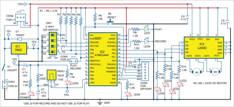
Once the circuit (or hardware) is ready, burn Remote_Robot.hex code to ATmega8A.
When power switch S1 is switched on, LED2 through LED7 glow for a while and turn off (self-test). Then, either LED6 or LED7 glows, indicating record or play mode, respectively. The mode depends on the setting of jumper J2.
In record mode, J2 is connected to the circuit and in play mode J2 is open. Press the required button on the remote once to record it. Then, permanently set J2 to play mode (that is, remove J2). If you want to change the code to other buttons, connect J2 to record mode.
For initial setup, either disconnect motors M1 and M2, or remove 5V/9V supply from J1 and then connect J2. Now, set the address code for the data (remote key) to be stored in the MCU using DIP switch DIP1 (using S2 through S5).
After setting the 4-bit address in hexadecimal code (say, 0101h), switch on the power using S1. After self-test, LED6 will glow, indicating the mode as recording. Press a button (say, 2) on the remote. LED9 will blink, indicating that a signal/data is received by IRRX1 sensor. This signal is fed to the MCU, which processes and saves data in its inbuilt EEPROM.
At the same time, a visual indication of the address being assigned for each data is indicated by the glowing of corresponding LED2 through LED5 in equivalent hexadecimal format.
Data being saved is acknowledged by the blinking of LED7. This process can be repeated for up to 16 required codes (0 to F hex).
For easy control of the robot, we have assigned the code (or bits) to five buttons of the remote control as listed in Table I.
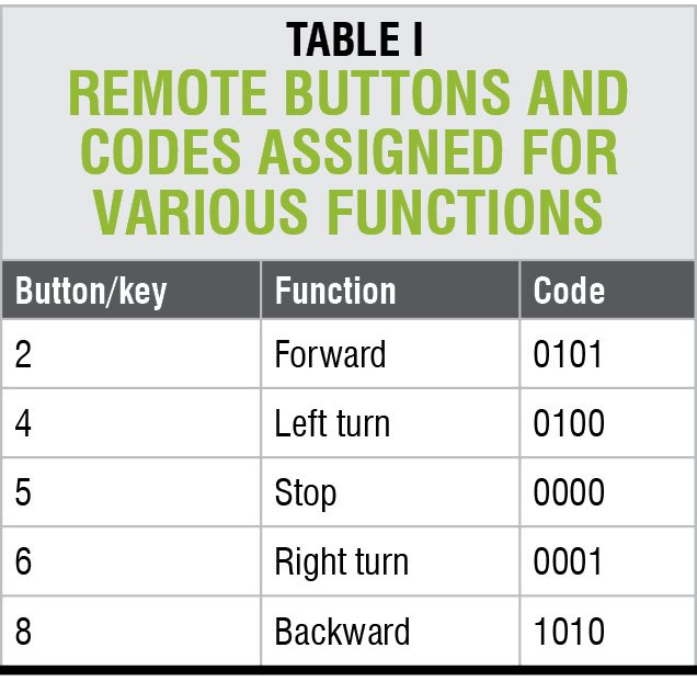
For any other button, the code is set as stop (0000). So to stop the robot in an emergency case, press any other button on the remote.
After recording the required codes, remove J2 and press reset switch S6. After self-test, LED7 will glow, indicating that it is in play mode. Now, press the programmed remote button randomly and check that LED2 through LED5 indicate the required code. LED8 will blink for a while if there are errors like a button not pressed properly or signal not received properly.
Software
The software (remote_robot.c) is written in C language and compiled using Atmel Studio. AVR PROGISP programmer is used for programming the MCU during testing. However, you can use any suitable programmer for the same.
Burn remote_robot.hex file to the MCU through ISP port. Since the MCU uses an internal oscillator, set the fuse bits to the default value as shown in Fig. 2.
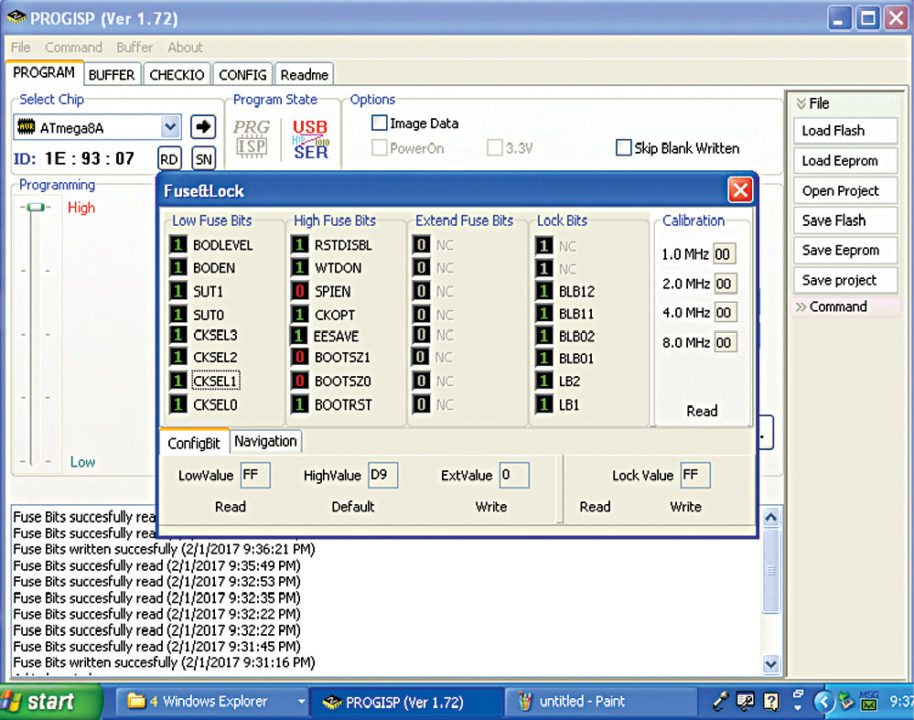
Note. As per datasheet of ATmega8A, fuse setting 1 means unprogrammed and 0 means programmed.
Download source code
Construction and Testing
A single-side PCB layout for the remote-controlled robot is shown in Fig. 3 and its components layout in Fig. 4. After assembling the circuit, place the populated PCB and 9V battery on the chasis of the robot. J1 is used to select 5V or 9V power supply depending on 5V DC motors or 9V DC motors used.
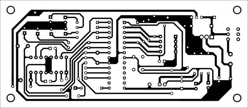
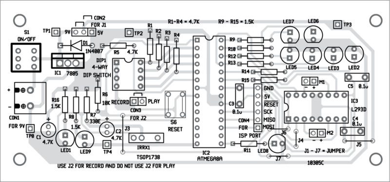
Download PCB and component layout PDFs: click here
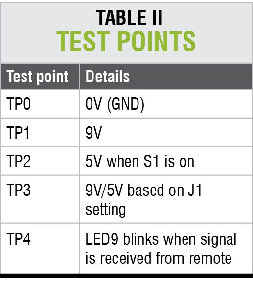
Use of an IC base/socket is recommended for the MCU. Connect M1 and M2 to the PCB through twin-wire external wires. Before running the robot, verify the voltages are as shown in Table II. Your remote-controlled robot is ready to use!


Hello sir given good information about remote control robot and give demo videos in that project
Please send your request for video of this project to [email protected]
Is there any video or images of finished product !?
Please send your request to [email protected]. The complete kit of the project (unassembled) is available with Kits’n’Spares. Visit their website at http://www.kitsnspares.com