 We generally measure voltages with a multimeter or a voltmeter. But you can also measure low-value DC voltages up to 5V that are generally found in electronics circuits with this laptometer and see their value on laptop monitor.
For this an Arduino Uno board’s serial communication function comes in handy for programming and displaying the voltages on laptop monitor using Arduino IDE and processing software. The Arduino Uno board used for measurements is shown in Fig. 1.

The Arduino Uno board is an AVR ATmega328P microcontroller based development board with 6 analogue input pins and 14 digital I/O pins. The microcontroller has 32kB ISP flash memory, 2kB RAM, and 1kB EEPROM, and can operate at clock frequency of 16MHz.
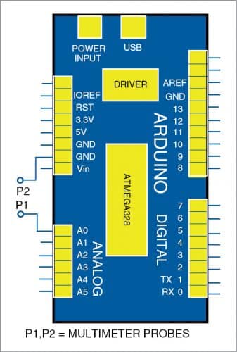
The board provides capability of serial communication via UART, SPI, and I2C. In this project, Arduino Uno is used for communication between the voltage point and laptop display through serial communication. Its analogue input pin A0 is used here as input point by connecting positive terminal of voltage source to A0 pin and negative terminal to GND pin of Arduino Uno.
The simple arrangement required for voltage measurements is shown in Fig. 2. Voltage measuring probes P1 and P2 are connected across analogue pin A0 and GND pin of Arduino Uno.

When you measure voltage, the voltage received at A0 pin changes to corresponding digital value. As Arduino Uno has 10-bit ADC, the range of input analogue value is mapped as 0 to 1023, with full-scale voltage at 5V. So, for each digital level change, the voltage will be 5/1023 volts.
A part of the code written in Arduino IDE for voltage conversion is given below.
voltage_value = analogRead(voltage_pin);
delay(100);
voltage_V = (voltage_value * 5/1023);
Serial.println(voltage_V);
If 2.5V is received at analogue pin A0 as ‘voltage value’ in the code, its corresponding digital value will be 2.5/5 multiplied by 1023, that is, 512. And if you know the digital value (512), multiply it with 5/1023 to extract the voltage (2.5V).
The input voltage is processed by Arduino Uno and sent to laptop through serial communication. The code in laptop reads the voltage and displays on its monitor.
The usual multimeter probes may be used for connection to A0 and GND pins of Arduino as shown in Fig. 2.
The Processing software used for coding is a flexible sketchbook and a language for learning to code within the context of the visual arts. We will write the program using this language to receive voltage values from serial port. Part of the Processing code to receive the value from serial port is given below.
void serialEvent(Serial my_port)
{
value = float(my_port.
readStringUntil(‘\n’));
}
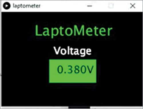
The user interface layout to display voltage using Processing code is shown in Fig. 3. You can place the layout on the laptop’s Desktop as shown in Fig. 4.


7Arduino code efyLaptom.ino was used for the author’s prototype. It must be compiled and uploaded to Arduino Uno using Arduino IDE. In the layout designing part, Processing code efydeslaptom.pde is used for this project.
Construction and testing
Connect Arduino IDE to laptop through any available COM port using a USB cable. Identify the exact COM port from the Device Manager. Then open the efyLaptom.ino Arduino code. This code must be compiled and uploaded to Arduino Uno using Arduino IDE.
Next, design the user interface layout using Processing software. Download Processing software, extract the files and click on processing.exe file. Processing environment will open. Open efydeslaptom.pde to run it. Make sure that the COM port used in Processing should be the same as used in Arduino code. (In the prototype Arduino was connected to laptop through COM6, and the same was used in Processing code as well.)
Before using the Processing application, make sure your Arduino is programmed and connected to laptop through COM port. When Processing is run, a Dialog box will pop up as shown in Fig. 3.
Now, to measure any DC voltage up to 5V, use multimeter probes P1 and P2 at specific test points with respect to ground.
This arrangement can be used as a USB multimeter when you do not have a proper multimeter at home, though it is not handy enough to be carried around. However, it has the scope to expand its features to measure current and resistance as well like a normal multimeter.
Download Source Code
Pradipta Ghosh is M.E. in electronics and instrumentation, currently working as project site engineer (Signal and Telecom) at Indian Port Rail and Ropeway Corporation Limited. He is passionate about electronics and MCU based embedded system applications


