 Described here is a simple metal detector circuit that can detect metallic conductors in its vicinity up to a range of 25 to 30 millimetres. Concealed metallic objects such as metal foils enclosed in a plastic cover, e.g., toothpaste tubes, and small objects like refill tips made of magnetic materials too can be detected using this circuit. However, very thin metallic foils may go undetected due to a large resistance.
Metal detector circuit
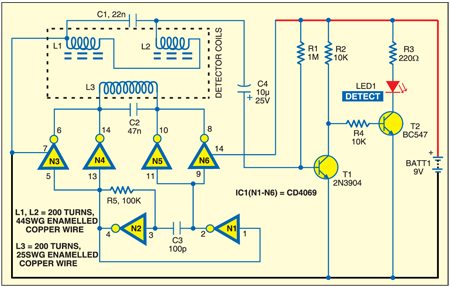
The circuit is based on the principle of a difference resonator and consists of inverters, detector coils, capacitors and transistors as shown below.

You can design a longer-range model on similar principles by using higher power and larger dimensions of detector coils.
Operating theory
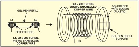
The working of this metal detector circuit is based on detecting the magnetic field produced by Eddy currents generated in a conductor when it is placed in a varying magnetic field. The detector circuit is formed by coils L1, L2 and L3. Coils L1 and L2, each having 200 turns of 44SWG (0.08mm diametre) enameled copper wire, are wound on a gel-pen refill. Two small ferrite rods are inserted into the gel-pen refill and fixed at both ends using glue as shown here.

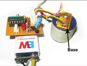
Fix the refill on a base (support), such as a small general-purpose PCB, using glue. Fix the gel-pen refill PCB on one end of a 50gm solder wire bobbin such that the refill is in the centre of the bobbin.
Coil L3, having 200 turns of 25SWG (0.5mm diametre) enameled copper wire, is wound on the solder wire bobbin. Varying magnetic field produced in coil L3 induces current in coils L1 and L2. Coils L1 and L2 in series form a difference resonator along with capacitor C1. Coil L3 itself is made to resonate by driving it with a square-wave signal at a frequency approximately equal to the resonance frequency of the L-C circuit formed by outer coil L3 and capacitor C2.
The square wave is generated by the oscillator formed by gates N1 and N2 (IC CD4069). Gates N3 through N6 act as buffers to drive outer coil L3. This produces sinusoidal current in coil L3, producing sinusoidal magnetic field mutually coupling the inner two coils.
Circuit operation
When a metal (conductor) is brought near one of the inner coils, say L1, the Eddy currents in the conductor reduce the magnetic flux in coil L1, reducing the induced electromotive force (emf). This means a difference-signal is produced by the two coils due to the presence of a conducting object (metal) near coil L1 as shown in the circuit. Coils L1 and L2 are connected such that the difference of the induced emf is fed to transistor T1 through capacitor C4. Transistor T1 is configured as a small signal amplifier.
The amplifier is biased using a large base resistor of 1 mega-ohm. The AC-difference signal directly appears across the base-emitter junction of transistor T1 producing changes in the emitter current. This results in a voltage change in the collector of T1, which drives transistor T2 to glow LED1.
A small signal produced due to the magnetic field of Eddy currents in a small piece of metal like a screw or nut is sufficient to trigger T2 through T1.
Normally, the ferrite rods within coils L1 and L2 are adjusted such that the difference-signal from them is minimum. In this particular design, it is possible to adjust the signal to a voltage as small as 5 mV of sine wave. Transistor T2 plays the role of an electronic switch to drive LED1, which acts as a visual indicator whenever the metal is detected.
Thus when the detector assembly is brought close to a conductor, LED1 glows. You can change capacitors C1 and C2 on trial-and-error basis and fix the value for maximum sensitivity to select a resonant frequency and drive the oscillator (N1 and N2) at that frequency. Here a frequency of 55 kHz has been selected.
Note:
Make sure that the two resonators (one formed by L1 and L2 in series and other by L3) have approximately the same frequency of resonance.
The frequency of resonance of an L-C circuit is given by:![]()
The frequency of an R-C oscillator using gates is given by:![]()
You can vary R5 and C3 values using variable resistors and capacitors to fine-tune the frequency.
Construction & testing
Assemble the metal detector circuit on a general purpose PCB and enclose in a suitable small cabinet. Terminate all the four terminals of the coils on the PCB base for connecting the coils to the main circuit. The gel-pen refill should be sufficiently rugged. Secure it firmly inside the bobbin using non-magnetic, non-conducting materials. The ferrite rods too must be sufficiently secured in their positions using a synthetic enamel. Even a slight unintentional displacement can upset the balance of the resonator drastically. So use of a screw-type ferrite rod is recommended.

For detector coil assembly, first insert one of the ferrite rods in the front end of the detector such that it is just inside the gel refill tube. Now insert the second ferrite rod in the other end of the tube. At this point, LED1 should glow brightly. Push the ferrite rod very slowly inside the tube while watching LED1. As soon as LED1 goes off, stop pushing the rod, mark the position of the rod and fix it in the tube using glue. Now the detector is well adjusted and ready for use.
The project was first published in October 2011 and has recently been updated.


