


 To make a great solder joint, component preparation is a must. It is very important to clean component leads, wires and contact surfaces prior to soldering with isopropyl alcohol. Remember, tinning component leads and wires makes the actual soldering of joints quick and efficient. Tinning involves putting a thin layer of solder on the component/wire tips, which assists greatly in transfer of heat to solder joints.
Obviously you need to strip the enamel off the copper wire (ECW/magnet wire) to prepare it for soldering. However, tinning a small-gauge wire (>18SWG) using an ordinary soldering iron is quite cumbersome.
You can use this home-made micro-solder pot not only to strip the heat-strippable enamel but also to put a thin layer of solder on the stripped part. Note that wire leads that are insulated with non-heat-strippable enamel should be scraped clean before the micro-tinning process.

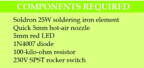
This do-it-yourself project is a true recycling project as it turns the popular soldering iron element into a micro-solder pot for your electronics lab. At the heart of this project is a 25W soldering iron element from Soldron (Fig. 1). Another main component required is a standard 5mm hot-air nozzle for the quick hot-air SMD rework station as shown in Fig. 2. Apart from these, you only need a handful of inexpensive components and accessories as mentioned in the parts list!
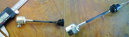

Fig. 1: Soldering element with nozzle
Construction
First, plug the hot-air nozzle directly into the tip of the soldering iron element. Then secure the nozzle over the tip using a high-temperature sealant/adhesive. The nozzle forms the solder pot. When the soldering element is heated up, the nozzle too becomes hot. Fig. 1 shows an example of micro-solder pot constructed in this way.
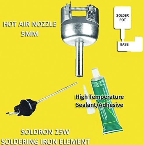
Fig. 2: Nozzle and other accessories
Fig. 3 shows a very simple power supply circuit, which can be easily constructed on a small piece of perforated prototyping board. The 230V AC power line voltage is fed to the soldering iron element through the on/off switch. The 1N4007 diode converts the 230V AC mains into a safe power supply voltage for the soldering iron element. The red LED indicates the power on/off status.
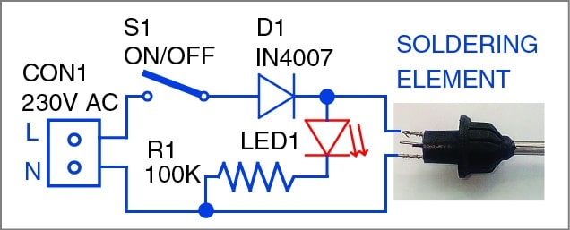
Fig. 3: Circuit of the micro-solder pot power supply
Tinning procedure
Fill your micro-solder pot with adequate amount of solder wire, switch it ‘on’ and let it heat up to the right temperature. As the temperature of the pot rises, you can see the solder wire in the pot melting away. After a few minutes, you can see molten solder in the pot. Next, determine the length of the wire/component lead which must be stripped. Insert the lead end of the wire into the solder pot and wait for a few seconds. Finally, slowly pull the lead back out of the solder pot. No doubt, what you get is a nicely tinned wire/component lead! Fig. 4 shows tinning on a stripped wire end.
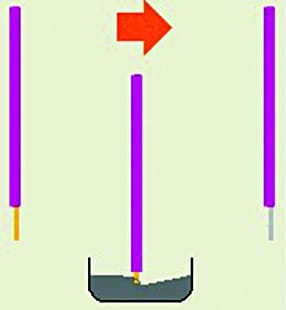
Fig. 4: Tinning before and after
Caution. This micro-solder pot is meant for experienced electronics hobbyists.
Inexperienced persons unfamiliar with heat soldering tools and molten solder characteristics should not use it. To this effect, provide a warning notice on the use of the hot pot.
