


A tachometer is nothing but a simple electronic digital transducer. Normally, it is used for measuring the speed of a rotating shaft. The number of revolutions per minute (rpm) is valuable information for understanding any rotational system.
Check RPM Measurement Sensors and Techniques.
For example, there is an optimum speed for drilling a particular-size hole in a particular metal piece; there is an ideal sanding disk speed that depends on the material being finished. You may also want to measure the speed of the fans you use.

This easy-to-make microcontroller-based tachometer measures the rpm of most shop-floor tools and many household machines without any mechanical or electrical interface.
Working of a Microcontroller-based Tachometer
Just point the light-sensitive probe tip atop the spinning shaft towards the spinning blade, disk or chuck and read the rpm. The only requirement is that you first place a contrasting colour mask. A strip of white adhesive tape is ideal on the spinning object. Position it such that the intensity of light reflected from the object’s surface changes as it rotates.
Each time the tape spins past the probe, the momentary increase in reflected light is detected by the phototransistor. The signal processor and microcontroller circuit count the increase in the number of such light reflections sensed by it and thereby evaluate the rpm, which is displayed on the 4-digit, 7-segment display.
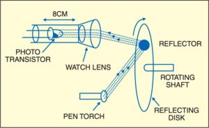
The phototransistor is kept inside a plastic tube, which has a convex lens fitted at one end. A convex lens of about 1cm diameter and 8-10cm focal length is a common item used by watch repairers and in cine film viewer toys. It can be obtained from them to set up the experiment.
The phototransistor is fixed on a piece of cardboard such that it faces the lens at a distance of about 8 cm. The leads from the phototransistor are taken out and connected in the circuit shown in Fig. 1. Fig. 2 shows a suitable arrangement of the phototransistor.
The detected signal is amplified by transistor 2N2222 (T5) and further amplified by operational amplifier CA3140 (IC3). The reference voltage point for the operational amplifier is obtained by a resistor divider network comprising R2 and R3. The output from pin 6 of IC3 is fed to pin 12 of the microcontroller AT89C2051.
Note that pins 12 and 13 of the microcontroller AT89C2051 are the inputs (+ and -) of its internal analogue comparator. Pin 13 is adjusted to nearly half the supply voltage using a potential divider comprising resistor R7 and preset VR1 across the supply.
The pulses picked up by the phototransistor are sensed by the internal comparator of AT89C2051, and, through software, each pulse representing one rotation of the object is detected. By counting the number of such pulses, on an average per-minute basis, the RPM is evaluated. It is displayed by a software routine to light up the LED segments of the 4-digit, 7-segment display.
Circuit Description
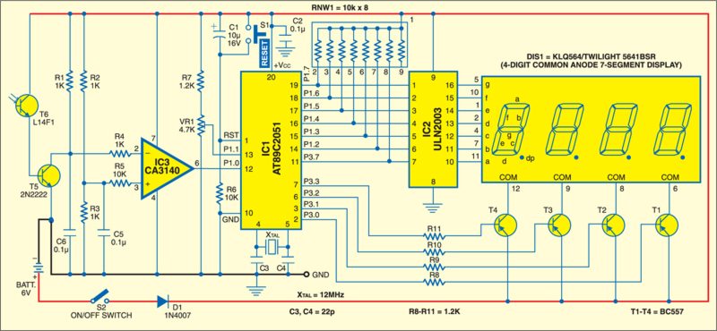
Fig. 1 shows the circuit of the digital tachometer. The tachometer comprises AT89C2051 microcontroller, ULN2003 high-current Darlington transistor array, CA3140 operational amplifier, common-anode 7-segment (4-digit multiplexed) display and its four anode-driving transistors.
The AT89C2051 is a 20-pin, 8-bit microcontroller of Intel’s 8051 family made by Atmel Corporation. Port-1 pins P1.7 through P1.2, and port-3 pin P3.7 are connected to input pins 1 through 7 of ULN2003. Port-1 pins are pulled up with a 10-kilo-ohm resistor network RNW1. They drive all seven segments of the display with the help of internal inverters.
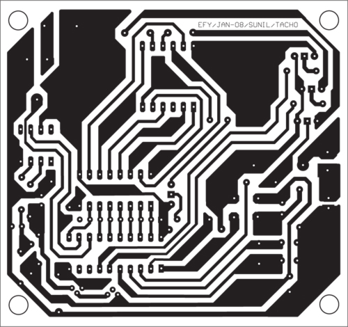
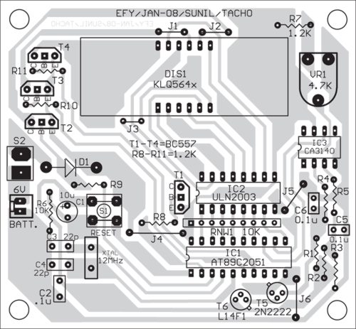
Download PCB and component layout PDFs: click here
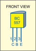
Port-3 pins P3.0 through P3.3 of the microcontroller are connected to the base of transistors T1 through T4, respectively, to select one digit out of the four at a time and to supply anode-drive currents to the common anode pin of the respective digit. The pin configuration of transistor BC557 is shown in Fig. 3.
When pin P3.0 of microcontroller IC1 goes low, it drives transistor T1 into saturation, which provides the drive current to anode pin 6 of the 4-digit, 7-segment, common-anode display DIS1. Similarly, transistors T2 through T4, respectively, provide supply to common-anode pins 8, 9 and 12 of DIS1. Thus, microcontroller IC1 drives the segment in a multiplexed manner using its port pins. This is a time-division multiplexing process.
Segment data and display-enabled pulse for display are refreshed every 5 ms. Thus, the display appears to be continuous even though it lights up one by one.
Switch S1 is used to manually reset the microcontroller, while the power-on-reset signal for the microcontroller is given by C1 and R6. A 12MHz crystal is connected to pins 4 and 5 of IC1 to generate the basic clock frequency for the microcontroller. The circuit uses a 6V battery for power supply, or a mains-derived low-voltage supply. An actual-size, single-sided PCB layout for the tachometer (Fig. 1) is shown in Fig. 4 and its component layout in Fig. 5.
Construction and Testing
The source code of this article can be downloaded from the code file given at the end of the article. Using a programmer, load the code into the new chip AT89C2051. Then, fit it into the circuit board, and after powering up the circuit, test it.
For testing, point the probe using torchlight for illumination of the rotating object. For fans, use the light from behind. Hold the probe firmly so as to provide a steady, bright illumination on the object. Even an LED pen torch could be used here. Avoid the fluctuating background light from sources such as tubelight.
Software
The software is written in Assembly language and assembled using the 8051 cross-assembler. It is well commented and easy to understand. It uses AT89C2051’s internal timer for measuring the period of one cycle of the rotation in units of 100 microseconds. Thus, if the speed is 1500 rpm, it is 25 rps, and the time taken for one cycle is 40 ms.
The timer uses an interrupt to count overflows every 100 microseconds, and so the number counted by the timer program in this case will be ‘400.’ This is divided by ‘600,000’ (so many 100/µs present in a minute), giving a result of ‘1500.’ This gives the RPM. These digits are displayed on the 4-digit, 7-segment display.
To perform the division, subroutine UDIV32 is employed, which is a standard subroutine available for the 8051 family for 32-bit number by 16-bit number division. It has an accuracy of 5 rpm in a 6000rpm count.
Related Techometer Projects
Download source code: click here
The article was originally published in July 2013 and has recently been updated in 2025.

I am happy to read these projects and please need or mentioned why u used value of register,capacitor and other component ?another values r used or this values are enough ?how to understand this is enough values?
I Had read this article.i need seven segment display continously on condition.where should i change in source code
Sir,
I am third year electronics engineering poly student. I am doing this digital tachometer as my 3rd year project. I completed everything. I even loaded hex file into the micro controller. But its not working. Please help. Is there any modification in program or hardware? Plz help.
Hi Sushil , did you complete the project fine
First you may test the circuit with proteus…. ?
IT WONT WORK
IT HAS SOME PROBLEM IN THE CODE
It was tested and working successfully. Please give your problems in detail
Can you please help I’m facing problem while running this circuit
Please give your problems in detail to help you solve the problem