It was in the middle of 1821 when J.T. Seebeck discovered that if two dissimilar metals connected at two different points are held at different temperatures, a microvoltage develops. This phenomenon is called Seebeck effect. Some years later, Peltier discovered that if a voltage is applied to a thermocouple, one junction of the thermocouple heats up while the other cools down. Opposite of the Seebeck effect is called the Peltier effect.
This guide to designing a little solid-state cooler engine is centered on the commonly available Peltier chip. A Peltier chip is a thermo-element that utilises the Peltier effect to implement a heat pump. It has two plates, one cold and the other hot. Between the plates there are several thermocouples connected together. If a proper voltage is applied, one plate becomes cold and the other plate becomes hot.
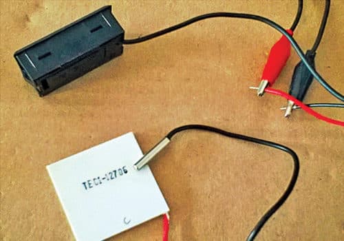
The Peltier chip is called a heat pump because it neither generates heat nor cold. It just transfers heat from one plate to another, thus cooling the first plate. It is also popularly called thermoelectric cooler (TEC) chip. In short, by applying a direct current (DC) to the TEC chip, temperature differences are generated between the front and back of the device (Peltier effect), and you end up with a hot and a cold surface. TEC1-12706 is a common thermoelectric cooler chip available from most eBay traders.
In TEC1-12706, the letter C after TE indicates ‘standard size,’ and 1 indicates ‘one-stage’ TEC. Right next comes a dash. After the dash, the first three digits indicate the number of thermocouples inside the TEC. Here, it has 127 couples. Next two numbers indicate operating current rating for the Peltier. So, 06 denotes ‘6 amperes.’
Peltier cooler
A Peltier cooler is a cooler engine comprising a Peltier element (TEC chip). When a direct current is passed through a TEC chip, the low-temperature side absorbs heat and the high-temperature side emits heat, creating a temperature difference across the two surfaces. However, since the heat emitted is more reactive to the amount of electricity input into the module than the heat absorbed, if a direct current is continuously passed through the chip the emitted heat exceeds the absorbed heat and both sides of the unit become hot. Because of this, it is crucial to connect the TEC chip to a radiator such as aluminium fins to efficiently disperse the emitted heat.
In short, when DC voltage is applied to the TEC chip, positive and negative charge carriers in the pellet array absorb heat energy from one substrate surface and release it to the substrate at the opposite side. The surface where heat energy is absorbed becomes cold, and the opposite surface where heat energy is released becomes hot!
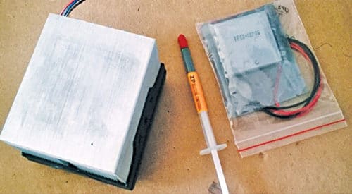
The Peltier cooler also includes a powerful heat-sink/fan combination to cool the TEC chip. Table below depicts specifications of a TEC1-12706 thermoelectric cooler chip. You can buy a CPU heat-sink and fan unit with almost the same specifications as the CPU fan for AMD processors: 80.6×80.6×69.4mm3 with aluminium fin heat-sink. The additional 60×60mm2 aluminium heat-sink plate (and thermal grease) is also available at reasonable price. Fortunately, you can buy most of these key components from prominent eBay and/or Amazon sellers (see Fig. 1).

TEC chip and basic test
Before starting an actual construction with a TEC chip, test it for proper working condition. For that, just connect the red (+) and black (-) wires of the TEC chip (TEC1-12706) to a 1.5V DC lab power supply and keep the power supply on for 10 to 30 seconds. Thereafter you can test the TEC chip using your fingertip or digital thermometer to ensure that one side of the chip is hot and the other side cold. Just mark down hot and cold faces of the TEC chip (for example, with letters H and C) using any permanent marker pen.

Powering up
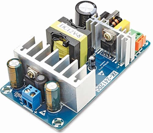
The assembled cooler engine (thermoelectric cooler chip, heat-sink and cooling fan, all assembled) can be powered from a 12V, 6A+ switch-mode power supply (SMPS) unit/module, like the one shown in Fig. 3. Else, try a 12V/7Ah SMF battery. If everything is okay, you will see traces of frost appearing on the plate within seconds.

Note that the primary function of a Peltier chip is cooling, and Peltier chips have different power ratings corresponding to how fast the cold side is able to cool down an object. Another factor generally specified is delta-T (dT), which is the maximum difference between temperature on both sides.
Further, Peltier chips don’t function as per specifications, unless there is something to help in taking the heat out from the hot side. That’s why a beefy heat-sink is called for. It’s the ambient air with its temperature where heat is dissipated.
Well, the assembled and tested cooler engine can now be used to build your own mini-refrigerator, can cooler or a tiny air-conditioner. A bit of googling will hopefully provide you fascinating ideas on that.
TEC controllers/drivers
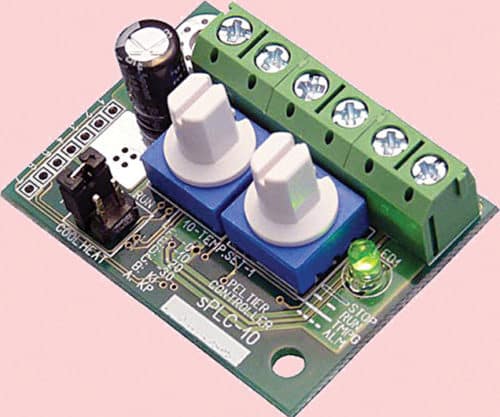
Sometimes you need a dedicated TEC controller/driver. Certainly, there are numerous devices available for advanced applications. On eBay, you can find several devices that would do the job. Fig. 4 shows such a feature-rich device, surprisingly with one feedback channel to accept inputs from an NTC thermistor for temperature stabilisation.

A TEC controller regulates the current supplied to the Peltier chip according to the desired temperature of the object and the actual measured object temperature. To be able to control the temperature of the object, you have to place the sensor on the object. Note that it’s important to place the sensor as close as possible to the critical point on the object where you need to maintain the desired temperature.
Since fan cooling of the heat-sink reduces thermal resistance from the heat-sink to the ambient air, most high-end TEC controllers have dedicated fan-control outputs backed by pulse-width modulation (PWM) technique. Therefore the fan increases the thermal performance and reduces the temperature difference (dT), allowing use of smaller heat-sinks.
Coefficient of performance
An important measure when selecting a Peltier element is the coefficient of performance (COP). COP is defined as the heat absorbed at the cold side divided by the input power of the Peltier element. The result of a maximum COP is minimum Peltier input power. Thus minimal total heat has to be dissipated by the heat-sink. The lower heat-sink temperature results in a lower dT. So smaller heat-sinks can be used, allowing a more space-saving design. On the other hand, when optimising costs, a design with a lower COP should be used.
DC or PWM?
There are two power supply/controller modes for thermoelectric coolers to operate by the Peltier effect: DC and PWM. Although in many situations PWM is used to drive Peltier elements, most Peltier element manufacturers suggest DC mode and explicitly advise against direct PWM control of Peltier elements.
It’s reported that Peltier elements controlled by PWM are always less efficient than applications controlled by DC. Another issue with PWM mode is electro-magnetic interference (EMI) in the wiring to the Peltier element.
Some experts recommend the use of PWM with an L-C filter to get a clean drive current at higher frequencies, while others prefer the comparatively simple DC mode. Anyway, according to documentations, it is important that the drive current is constant and smooth with very low ripple and noise to achieve good stability. Ripples reduce cooling capability of the Peltier element.
Linear or SMPS?
There are two popular solutions to generate the required DC for driving Peltier elements—linear and SMPS. Since Peltier elements/linear power supply units are driven by direct current, linear power supply units will work optimally but these have a poor efficiency. On the other hand, SMPS units have a high efficiency (>90%) as their electronic design leads to fewer losses. For this reason, linear power supplies are not recommended to drive Peltier elements.
Author’s note
This article shares the essentials and some ideas for the purpose of stimulating imagination and creativity. Readers can purchase most key components from eBay.in, and XK2412DC SMPS module and SPLC-10 Peltier controller from markets abroad.
This article was first published on 7 April 2018 and was updated on 17 January 2020.


Yes, it is possible to build many equipments for heating and cooling with Peltier cells. I’ve developed a lot about it and already own a mini-industry of these coolers and heaters.
Hi Alfonso. Im pretty excited about the TEC tecnology and am very interested in developing a few gadgets with this. I would like you assistance on how i can go about it if its not too much to ask and if you are comfortable sharing. Im based in Zimbabwe Africa.
what is the minimum temperature that is resulted with this above mentioned TEC at 12 v and 7 A.
can we go down to 0degree celcius by using this plate or with different TEC plate?
We can easily achieve subzero temperature within few seconds. As you know one side of the TEC becomes cool❄ while other side becomes hot🔥.
So you need to force cool the hot side to maintain the effective cooling on the cooler side. You can fix the TEC with thermal compound on CPU cooler heatsink with fan.