


 This mini ups circuit provides an uninterrupted power supply (UPS) to operate 12V, 9V and 5V DC-powered instruments at up to 1A current. The backup battery takes up the load without spikes or delay when the mains power gets interrupted. It can also be used as a work bench power supply that provides 12V, 9V and 5V operating voltages. The circuit immediately disconnects the load when the battery voltage reduces to 10.5V to prevent deep discharge of the battery. LED1 indication is provided to show the full charge voltage level of the battery. Miniature white LEDs (LED2 and LED3) are used as emergency lamps during power failure at night.
Mini UPS circuit
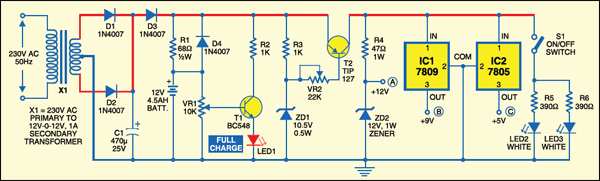
A standard step-down transformer provides 12V of AC, which is rectified by diodes D1 and D2. Capacitor C1 provides ripple-free DC to charge the battery and to the remaining circuit. When the mains power is on, diode D3 gets forward biased to charge the battery. Resistor R1 limits the charging current. Potentiometer VR1 (10k) with transistor T1 acts as the voltage comparator to indicate the voltage level. VR1 is so adjusted that LED1 is in the ‘off’ mode. when the battery is fully charged, LED1 glows indicating a full voltage level of 12V.
Mains power failure
When the mains power fails, diode D3 gets reverse biased and D4 gets forward biased so that the battery can automatically take up the load without any delay. When the battery voltage or input voltage falls below 10.5V, a cut-off circuit is used to prevent deep discharging of the battery. Resistor R3, zener diode ZD1 (10.5V) and transistor T2 form the cut-off circuit. When the voltage level is above 10.5V, transistor T2 conducts and its base becomes negative (as set by R3, VR2 and ZD1). But when the voltage reduces below 10.5V, the zener diode stops conduction and the base voltage of transistor T2 becomes positive. It goes into the ‘cut-off’ mode and prevents the current in the output stage. Preset VR2 (22k) adjusts the voltage below 0.6V to make T2 work if the voltage is above 10.5V.

Mains power back on
When power from the mains is available, all output voltages-12V, 9V and 5V-are ready to run the load. On the other hand, when the mains power is down, output voltages can run the load only when the battery is fully charged (as indicated by LED1). For the partially charged battery, only 9V and 5V are available. Also, no output is available when the voltage goes below 10.5V. If battery voltage varies between 10.5V and 13V, output at terminal A may also vary between 10.5V and 12V, when the UPS system is in battery mode.
Outputs at points B and C provide 9V and 5V, respectively, through regulator ICs (IC1 and IC2), while output A provides 12V through the zener diode. The emergency lamp uses two ultra-bright white LEDs (LED2 and LED3) with current limiting resistors R5 and R6. The lamp can be manually switched ‘on ‘and ‘off’ by S1. The circuit is assembled on a general-purpose PCB. There is adequate space between the components to avoid overlapping. Heat sinks for transistor T2 and regulator ICs (7809 and 7805) to dissipate heat are used.

Points to consider
The positive and negative rails should be strong enough to handle high current. Before connecting the circuit to the battery and transformer, connect it to a variable power supply. Provide 12V DC and adjust VR1 till LED1 glows. After setting the high voltage level, reduce the voltage to 10.5V and adjust VR2 till the output trips off. After the settings are complete, remove the variable power supply and connect a fully-charged battery to the terminals and see that LED1 is on. Once all the adjustments are made, connect the circuit to the battery and transformer & your mini ups system is good to go. The battery used in the circuit is a 12V, 4.5Ah UPS battery.
The article was first published in November 2009 and has recently been updated.


Whats stopping the battery from still being charged even after the battery is fully charged?
Can I replace the transformer with a 12V,200mA solar panal?
Sir, please Help me in this circuit.
i am connecting two loads in this circuit
one is 12v solenoid and other is 5v nodemcu development board but both are not working because of small current. what should i do .
the symbol of TIP 127 is correct (PNP) but connected wrong, the emitter should be connected to the positive rail and the collector should be on the regulators side.
I’ve tried this already.. promise.
Does this circuit protects the battery from overcharging.
12V battery floating voltage is around 13.8V. So is connecting a 12V source and adjusting the VR1 until “Full Charged” LED light up, correct ? Isn’t it a 13.8v source that should be connected for calibrating ?
I want to know about a few things:
1. Overcharge protection.
2. Output current.
3. Is it possible to replace the transformer with a potential divider?
sir can i use a magnetic choke(ballast) as a voltage devider to convert 220 v to 110 v
What is the easiest way to adapt this circuit to 24V?
Good day how can i step up the out put to 3 amps. Thank you
sir what will be response time, when there is power failure and i don’t want any lag in switching because its used for modem and i don’t want it to be turned off and take some time to back on, please tell me that do i nedd add some capacitors in the output, if yes tell me the value and by the way my modem uses 2amps, will i attain it if i use 2amp power supply.
Thankyou in advance
Most UPS response times lies between 5 milliseconds and 20 milliseconds. Not sure what response time for your application, adding capacitor here will not improve much and this is not for 2amp system but less than 1amp load.
Sir,
Greetings from Sri Lanka. could you advice me any modifications if I like to use three 18650 batteries instead of the 12 battery, so that it really looks a mini. Thanks.
Yes, you may also use three 18650 batteries instead of one 12V battery.