 Typically, implementing and testing even a small circuit requires an elaborate setup that includes breadboards, a dual DC power supply, hookup wires, ICs and resistors of different values. This setup can be quite messy and difficult to clean up at the end of the experiment. Also, the power supply can make the setup non-portable. Here we present a mobile electronic workbench that makes it easier for you to assemble and test circuits.
This mobile workbench is useful for students in schools, colleges, research institutions and industries alike. It can be used conveniently wherever you want. It is also cost-effective and very useful for giving demos. As the power is supplied by the batteries, the voltage is noise-free.
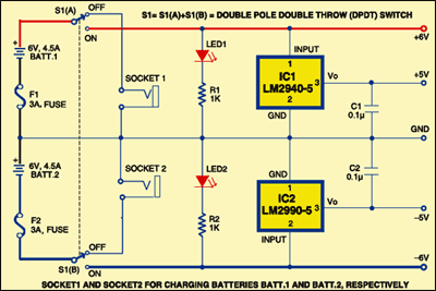
Fig. 1 shows the circuit of the mobile electronic workbench. Two low-drop-out (LDO) regulators (one positive and the other negative) are used here to provide regulated +5V and -5V for digital ICs.

When switch S1 is pushed to ‘on’ position, LEDs indicate the availability of voltages on the breadboard. When it is in ‘off’ position, the battery terminals connect to the sockets for charging the batteries. Apart from +6V and +5V supplies, you can also have a 12V source between +6V and -6V terminals.
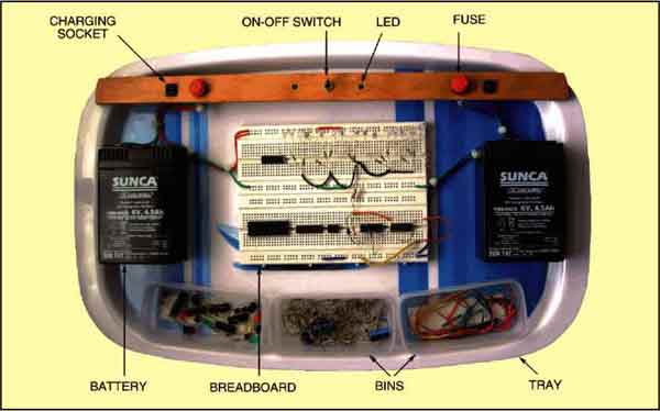
As shown in Fig. 2, the mobile workbench consists of a big melamine tray. At the centre of this tray, mount the breadboard. On the sides of the breadboard, stick two 6V, 4.5Ah maintenance-free lead-acid batteries (Batt.1 and Batt.2). On a wooden batten, mount two-pole, two-way toggle switch S1 and two fuses and two sockets symmetrically. Mount LED1 and LED2 on the sides of S1.

If you do not want this mobile workbench on a breadboard, you can assemble it on a general-purpose PCB and enclose in a suitable cabinet. Fix LEDs and switch S1 on the front panel of the cabinet and the fuses at the back side of the box.
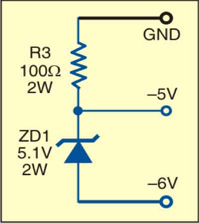
In place of LM2990-5, you can use a 5.1V, 2W zener diode with 100-ohm, 2W series limiting resistor as shown in Fig. 3.


