


 Mobile phone charger available in the market are quite expensive. The circuit presented here comes as a low cost alternative to charge mobile telephones/battery packs with a rating of 7.2 volts, such as Nokia 6110/6150.
Mobile phone charger circuit
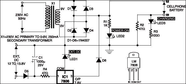
The 220-240V AC mains supply is down converted to 9V AC by transformer X1. The transformer output is rectified by diodes D1 through D4 wired in bridge configuration and the positive DC supply is directly connected to the charger’s output contact, while the negative terminal is connected through current limiting resistor R2.
LED2 works as a power indicator with resistor R1 serving as the current limiter and LED3 indicates the charging status. During the charging period, about 3 volts drop occurs across resistor R2, which turns on LED3 through resistor R3.

An external DC supply source (for instance, from a vehicle battery) can also be used to energise the charger, where resistor R4, after polarity protection diode D5, limits the input current to a safe value. The 3-terminal positive voltage regulator LM7806 (IC1) provides a constant voltage output of 7.8V DC since LED1 connected between the common terminal (pin 2) and ground rail of IC1 raises the output voltage to 7.8V DC. LED1 also serves as a power indicator for the external DC supply.
After constructing the circuit on a veroboard, enclose it in a suitable cabinet. A small heat sink is recommended for IC1.

The article was first published in January 2002 and has recently been updated.


I need electronic engineers for Mobile phone charger company.
Contact No. – +918826010536
Hi Anurag, If you want to post a job for the Electronics Engineers then please share it on our jobs website careers.electronicsforu.com.