 This project deals with the implementation of a process monitoring system using Arduino and MATLAB graphical user interface (GUI). One of the major application areas in instrumentation engineering deals with monitoring of various process parameters such as temperature, pressure, level, flow rate, pH, conductivity, viscosity, etc.
Process variable (PV) can either be displayed on an LCD and/or monitored on a PC in the control room. Along with the current value of PV, essential information such as maximum, minimum and mean value of PV are also provided in the display. Additionally, PC display also provides graphical trending of PV by the data acquisition (DAQ) software.
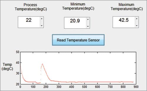
This GUI application built on MATLAB platform provides the following process monitoring system options: process temperature, maximum value of process temperature, minimum value of process temperature and real-time plotting of process temperature. GUI of this project is shown in Fig. 1.

Circuit and working
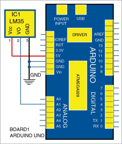
LM35 temperature sensor is connected to Arduino, as shown in Fig. 2.

Major components used in this project are as follows:
Arduino Uno board
This is an AVR ATmega328P microcontroller (MCU)-based development board with six analogue input pins and fourteen digital I/O pins. The MCU has 32kB ISP flash memory, 2kB RAM and 1kB EEPROM. The board provides capability of serial communication via UART, SPI and I2C. The MCU can operate at a clock frequency of 16MHz.
In this project, analogue pin A1 of Arduino is used to read output voltage from pin 2 of LM35 temperature sensor. Conversion from measured voltage to the corresponding value of temperature is carried out in the MATLAB source code.
LM35
This is a precision IC temperature sensor that provides output voltage, which is linearly proportional to temperature (in degree Celsius). LM35 exhibits typical accuracies of ±1⁄4°C at room temperature and ±3⁄4°C over a full temperature range of −55 to +150°C.
This sensor provides sensitivity of 10mV/°C.
In this project, Vout pin (pin 2) of LM35 IC is connected to analogue input pin A1 of Arduino. Pins 1 and 3 of LM35 are connected to +5V and GND of Arduino Uno, respectively.
Software
Steps for installation are given below.
- The GUI application programming is carried out in R2014a version of MATLAB. The procedure for installing Legacy MATLAB and Simulink Support for Arduino package is described in ‘Controlling A Robotic Car Using MATLAB-Based GUI’ DIY article published in October 2016 issue, and is also available on our website, www.electronicsforu.com
- After installing the package, open MATLAB source code file TemperatureLogger.m
- Edit the COM port number in a=arduino(‘COM7’)) line with the corresponding port number in the PC where Arduino has been installed.
- Click on Run in MATLAB.
- After successful communication is established (status can be observed in MATLAB Command window), click on Read Temperature Sensor in the GUI to monitor sensor data.
Download Source Folder
Note
You can extend the project to monitor and graphically trend PVs from multiple sensors. Computational flexibility and efficiency of MATLAB can be further explored in this project, with particular emphasis on frequency-domain analysis, to get a hands-on feel of analysing process information.
Shibendu Mahata is MTech (gold medallist) in instrumentation and electronics engineering from Jadavpur University. Currently, he is pursuing PhD from NIT Durgapur. He is interested in MCU-based real-time embedded signal processing and process control systems
Saikat Patra is passionate about electronics and MCU-based embedded system applications


To learn new technology