


 Metal oxide semiconductor field effect transistor (MOSFET) is a semiconductor device widely used for switching applications and amplifying electronic signals. While the facility to determine the type and pin configuration of bipolar junction transistors (BJTs) are available in digital multimeters (DMMs) used in the laboratory, most DMMs do not provide such features for MOSFETs.
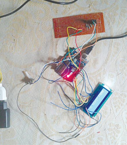
This Arduino-based project allows you to identify the type of MOSFET (p-channel or n-channel) and determine the pins that correspond to drain, source and gate terminals of MOSFET. The authors’ prototype is shown in Fig. 1.
Circuit and working for MOSFET Terminal Identification System
The circuit diagram of the MOSFET Terminal Identification System is shown in Fig. 2. The circuit is built around Arduino Uno board, 16×2 LCD (LCD1), three resistors (R1 through R3) and a few other components. MOSFET is a four-terminal device having source (S), gate (G), drain (D) and body (B) terminals.
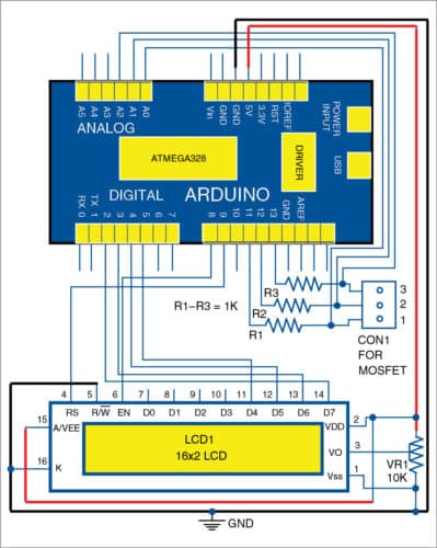
In most cases, body of the MOSFET is shorted with the source terminal. This makes it operate as a three-terminal device. For n-channel MOSFET (nMOS), D and S are n-type, while terminal B is p-type semiconductor material.
On the other hand, for p-channel MOSFET (pMOS), D and S are p-type, while terminal B is n-type semiconductor material.
As observed from Fig. 2, digital pins 11, 12 and 13 of Arduino UNO are used to apply input to an unknown device (test MOSFET). Whereas, analogue pins A0, A1 and A2 of Arduino UNO measure output voltage of the device. Note that, MOSFET (with front view) should be connected to the points marked 1, 2 and 3 in Fig. 2.
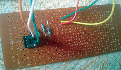
The authors’ prototype of the breakout board where MOSFET can be connected is shown in Fig. 3. Based on the voltage received through analogue pins, Arduino identifies the type of MOSFET and the terminals corresponding to each pin of MOSFET.
For display purposes, Arduino sends the information to the LCD1 via digital pins 5, 4, 3 and 2 to LCD1 pins D4, D5, D6 and D7, respectively. Note that, this project assumes source and body terminals of MOSFET to be internally shorted.
Software
The source code for MOSFET Terminal Identification System is written in Arduino programming language. ATmega328/328P is programmed using Arduino IDE software. Select the correct board from Tools->Board menu in Arduino IDE, and burn the program (sketch) through the standard USB port in your computer.
mosfet_find.ino code uses LiquidCrystal.h header file provided by Arduino library for working with LCD1.
lcd.begin(16, 2) function helps configure LCD1.
Serial.begin(9600) function initialises the serial port with a baud rate of 9600.
Download source code
Construction and testing
Assemble all components as per the circuit diagram. Adjust the preset for the full contrast of LCD1. Place MOSFET in connector CON1 for testing.
Shibendu Mahata (left) is M.Tech (gold medalist) in instrumentation and electronics engineering from Jadavpur University. He is interested in MCU-based real-time embedded signal processing and process control systems.
Souvik Kumar Das (right) is passionate about electronics and MCU-based system design
Is this useful for isolated mosfet device or not