 Like real movies, this circuit makes use of a characteristic of the human eye and brain known as the persistence of vision. A sequence of still pictures is projected onto a screen in rapid succession. The pictures differ slightly from one another and the brain interprets the succession of still pictures as continuous motion.
Here the pictures are shadows cast by low-voltage lamps. There are four Lamps in all, which glow in sequence cyclically. This gives the illusion of a simple but realistic movie.
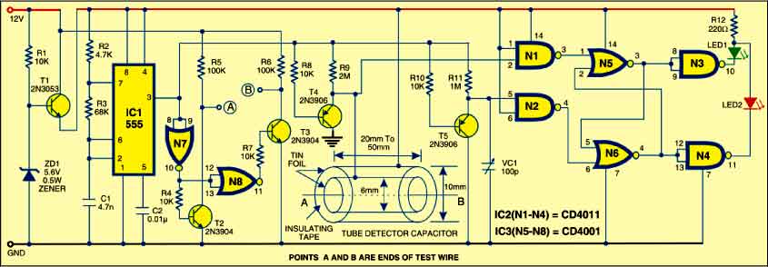
Fig. 1 shows the circuit for the movie maker. It is driven by clock pulses provided by NAND gates N1 and N2. The flickering frequency is adjustable through preset VR1. A suitable rate for perceiving continuous motion is 16 Hz. The clock pulses are fed to counter IC CD4022 (IC2). IC2 has eight outputs, but only the first four (0-3) are used in this circuit. The outputs go high one at a time, in sequence. The fifth output (output 4) is connected to the reset input so that the counter is immediately reset at the fifth count and the first output (output 0) goes high.
The counter outputs are fed to CD4049 hex buffer (IC3). The buffer outputs drive transistors T1 through T4 in a sequence. As each transistor conducts, the lamp connected to it glows. The lamps are rated at 0.3A so these provide enough light to operate the movie show in a dimly-lit room.

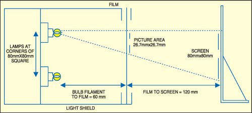
Assemble the circuit on a general-purpose PCB. Power-on the circuitusing switch S1 and make sure that the outputs of IC2 (0 through 3) are normally low but briefly go high three-four times within a second. Also ensure that the lamps flash one at a time in a repeating sequence. If the sequence appears to be wrong or any of the lamps fails to glow, check the wiring. The light shield and film holder can be made of a thin card, sheet metal or plywood. Strictly adhere to the various dimensions as shown in Fig. 2. Otherwise, the shadow images may fail to register properly when projected.
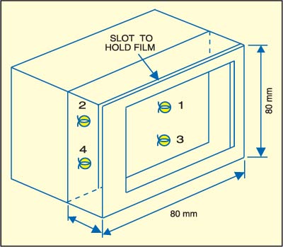
Use a plastic cabinet as shown in Fig. 3 to hold the circuit board and battery. Owing to the power requirements of the lamps, it is more economical to use four 1.5V cells in a battery box. Else, you can use a 6V power adaptor.

There are two ways of mounting the lamps. The more satisfactory but more expensive method is to bolt the four lamps. Alternatively, drill four 1cm dia. holes on the front of the cabinet, wedge the base of the lamps in these holes and solder wire to the bases.

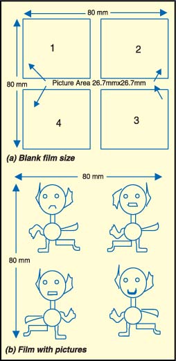
The easiest way to prepare the film frames is to photocopy the desired drawings onto transparent films. Alternatively, trace them on a transparent acetate film or draughtsman’s film, using a fine marker pen. Align all the drawings on the frames and project onto the screen.

Working of the circuit is simple. First of all, fix the clock frequency at about 16 Hz. Place the film on the holder. Ensure a distance of 12 cm between the screen and the assembled unit and power-on the circuit using switch S1. Now you can see your drawings as a short movie clip on the screen.
EFY note. We have tested this circuit without the mechanical arrangement.


