


We designed a Multi Switch Control Circuit to control a buzzer or an appliance using multiple switches located in different areas.
Many electronics enthusiasts enjoy designing customised control circuits. Here, we explore an interesting circuit that enables a single buzzer/appliance through multiple switches that may be located in different areas or rooms.
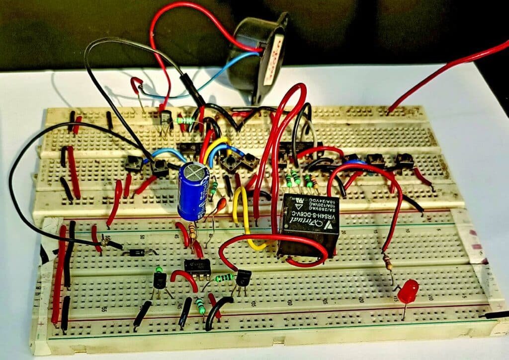
The prototype for Multi switch control circuit is shown in Fig. 1. As can be seen in the figure, the upper side the breadboard is used for multi-switch control of the buzzer, while its lower side is used for multi-switch control of an appliance.

| Parts List: Multi switch control circuit for buzzer/appliances | |
| Semiconductors: | |
| IC1 | –LM7805, 5V voltage regulator |
| IC2 (IC2A-IC2E), IC3 (IC3A-IC3E) | -74LS86 quad EX-OR gate |
| T1 | -2N2219 npn transistor |
| BR1 | -1A bridge rectifier |
| LED1 | -5mm LED |
| Resistors (all 1/4-watt, ±5% carbon): | |
| R1-R10 | -1-kilo-ohm |
| Capacitors: | |
| C1 | -1000μF, 35V electrolytic |
| Miscellaneous: | |
| CON1 | -2-pin connector |
| CON2 | -4-pin male connector |
| S1-S8 | -Push-to-on switch |
| PZ1 | -Buzzer |
| X1 | -230V AC primary to 15V, 500mA secondary transformer |
Multi Switch Control Circuit Diagram
The circuit diagram of the multi-switch control for the buzzer is shown in Fig. 2. It is built around a step-down transformer (X1), bridge rectifier (BR1), 5V voltage regulator 7805 (IC1), two exclusive OR gate 74LS86 ICs (IC2, IC3), buzzer (PZ1), and a few other components.
This circuit utilises two 74LS86 quad 2-input XOR gates to control the buzzer with 8 push-to-on switches (S1 through S8). One end of the eight switches is connected to 5V DC, while the other end is connected to the junctions of one input of an XOR gate and one end of 1-kilohm resistors (R2 through R9).

The other ends of the eight resistors are pulled down to ground. Adding pull-down resistors ensures that the inputs of the XOR gates have defined low logic levels when the switches are not pressed.
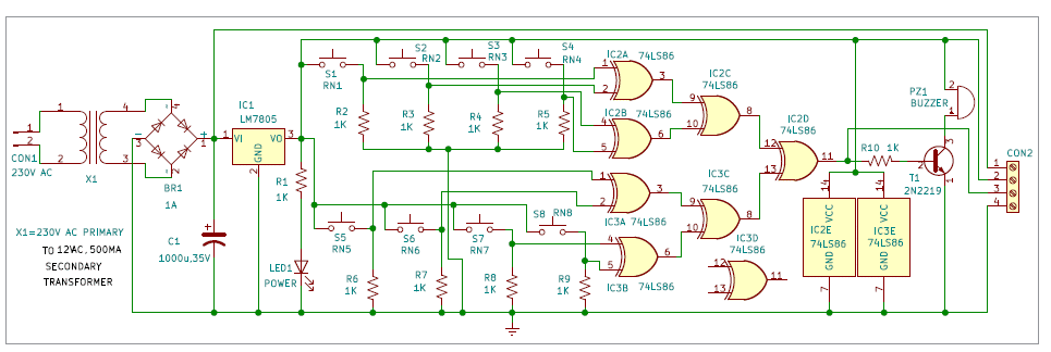
The outputs of the XOR gates are interconnected in such a way that if any one of the switches is pressed, the output of the last XOR gate (IC2D) will be high. Transistor T1 is connected to the output pin 11 of the XOR gate IC2D via resistor R10.
The buzzer is connected between the collector of transistor T1 and 5V DC. When any of the switches (S1 through S8) is pressed, the buzzer gets activated to produce an audible alarm.

The circuit requires 5V DC to operate, which is derived from the 12V, 500mA secondary transformer X1. The 230V AC mains supply is connected to the primary of X1 via CON1 in the circuit. The 12V AC secondary is connected to bridge rectifier BR1 for rectification.
The rectified voltage is filtered by capacitor C1 and given to the input of LM7805 to obtain regulated 5V for the circuit’s operation. Additionally, it is used to drive relay RL2 used in the optional circuit. The glowing of LED1 indicates the availability of 5V.
The IC 74LS86 contains four individual two-input EX-OR gates. An exclusive OR gate, often abbreviated as EX-OR, performs the logic that the output of a 2-input exclusive OR gate becomes high if one and only one input will be high. For proper understanding of the device, refer to Table 1, which clarifies that the buzzer sounds only when one switch (out of 8) is pressed.
| Table 1: Buzzer on/off / appliance on/off | ||||||||||
| S1 | S2 | S3 | S4 | S5 | S6 | S7 | S8 | Pin11 of IC2D | Buzzer on/off status when switch is pressed | Appliance is on for 1-15 minutes based on VR1 setting |
| 0 | 0 | 0 | 0 | 0 | 0 | 0 | 0 | 0 | off | off |
| 1 | 0 | 0 | 0 | 0 | 0 | 0 | 0 | 1 | on | on |
| 0 | 1 | 0 | 0 | 0 | 0 | 0 | 0 | 1 | on | on |
| 0 | 0 | 1 | 0 | 0 | 0 | 0 | 0 | 1 | on | on |
| 0 | 0 | 0 | 1 | 0 | 0 | 0 | 0 | 1 | on | on |
| 0 | 0 | 0 | 0 | 1 | 0 | 0 | 0 | 1 | on | on |
| 0 | 0 | 0 | 0 | 0 | 1 | 0 | 0 | 1 | on | on |
| 0 | 1 | 0 | 0 | 0 | 0 | 1 | 0 | 1 | on | on |
| 0 | 0 | 0 | 0 | 0 | 0 | 0 | 1 | 1 | on | on |
Construction and Testing
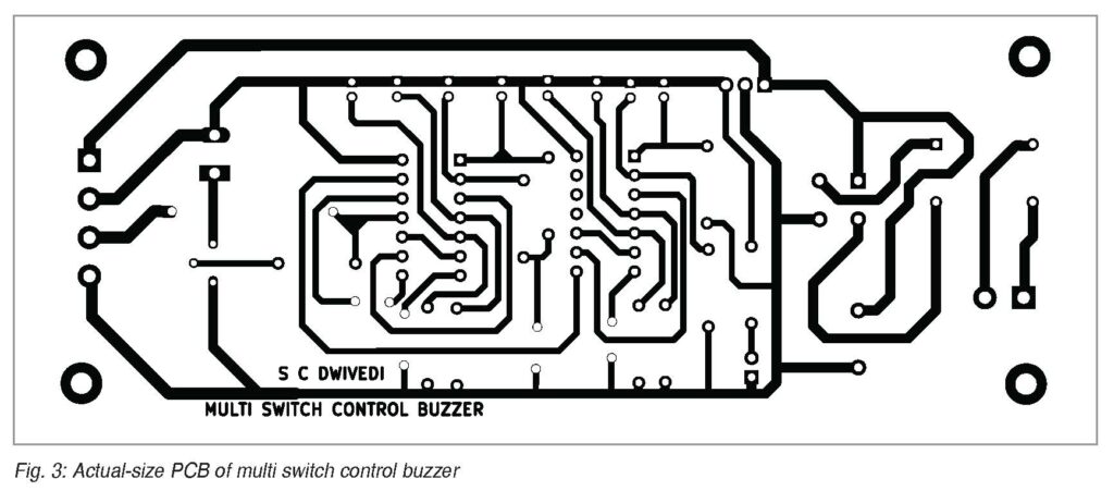
An actual-size, single-side PCB layout for the multi-switch control buzzer circuit is shown in Fig. 3 and its component layout in Fig. 4. After assembling the circuit on PCB, enclose it in a suitable box. Fix LED1 and buzzer in front of the box. Place the switches (S1 through S8) through twin flexible wires in different room numbers (RN1 through RN8) for operating the buzzer.
After assembling the components, install the unit near the common room in such a way that when somebody from any room number (RN1 through RN8) presses any switch, the buzzer sounds there to draw attention of the concerned person(s). CON2 is used for the optional appliance control.


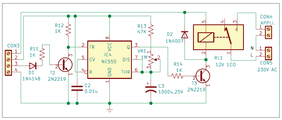
Optional Circuit (Appliance Control)
The circuit diagram for appliance control is shown in Fig. 5. It is built around timer NE555 (IC4), two transistors 2N2219 (T2 and T3), 12V one changeover (SPDT) relay, and a few other components. This circuit is controlled by the buzzer circuit by interconnecting CON2 and CON3 and removing the buzzer.
The working of this circuit is similar to the buzzer circuit. When any of the switches (S1 through S8) is pressed, IC4 triggers for a preset time, and the appliance gets switched on for the preset time, and thereafter switches off automatically.
| Table 2: Appliance-on timing | ||
| Value of R = (R13+VR1) | Value of C= C3=1000µF, 25V | Appliance on |
| 55k set via VR1 | 1000µF | 1 minute |
| 272.7k set via VR1 | 1000µF | 5 minutes |
| 545.4k set via VR1 | 1000µF | 10 minutes |
| 818.2k set via VR1 | 1000µF | 15 minutes |
For proper understanding of the device, refer to Table 1, which indicates that the appliance will be enabled for a preset time when one switch (out of 8) is pressed momentarily.
An actual-size, single-side PCB layout for the optional appliance control circuit is shown in Fig. 5 and its component layout in Fig. 6. After assembling the circuit on PCB, enclose it in a suitable box. Interconnect CON2 and CON3 through male and female connectors.
Now your appliance control device is ready to use. After powering on the circuit, press any switch among S1 through S8 from different room numbers (RN1 through RN8) to operate the appliance for a preset time.
| Parts List: Optional (Appliance Control) | |
| Semiconductors: | |
| IC4 | -NE555 timer |
| T2, T3 | -2N2219 npn transitor |
| D1 | -1N4148 signal timer |
| D2 | -1N4007 rectifier diode |
| Resistors (all 1/4-watt, ±5% carbon): | |
| R11, R12, R14 | -1-kilo-ohm |
| R13 | -47-kilo-ohm |
| VR1 | -1-mega-ohm potentiometer |
| Capacitors: | |
| C2 | -1000μF, 35V electrolytic |
| C3 | -1000μF, 25V electrolytic |
| Miscellaneous: | |
| CON3 | -2-pin female connector |
| CON4 | -2-pin connector |
| CON5 | -2-pin connector |
| RL1 | -12V, 1 changeover (1CO) relay |
Timer IC4 with RC components decides the time available at output pin 3 to switch on the appliance via relay RL1. Here in RC, R is equal to (R13+VR1) and C is equal to C3 (1000µF). These time-deciding RC components can be set for 1 minute to 15 minutes, as shown in Table 2.
The 555 timers must be configured in monostable mode. The 555 timer IC4 starts timing when it triggers via switches S1 through S8 and switches on the appliance. Generally, the time duration for pin 3 of 555 timer IC will remain high. Its value can be derived from the relationship: T=1.1xRxC
For making a 1-minute timer circuit, you can calculate the value of the resistor (VR1+R13) to be around 55k. Similarly, for the 5-minute, 10-minute, and 15-minute timer circuits, the resistor values are 272.7k, 545.4k, and 818.2k, respectively. After the set preset time the appliance will switch off automatically.
After assembling the circuit, install the unit near the appliance to be controlled in such a way that when somebody from any room number (RN1 through RN8) presses their switch, the appliance gets switched on for the preset time.
Bonus: Check the complete step-by-step video tutorial to make this project:
S.C. Dwivedi is an electronics enthusiast and circuit designer at EFY