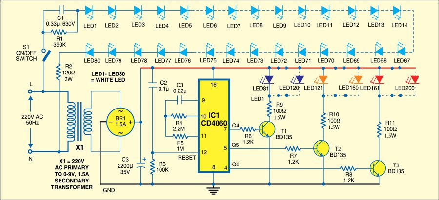
 This circuit comprises two parts: a string of 5mm high-intensity white LEDs connected in series and the circuit wired around. IC CD4060 with an inbuilt oscillator. The IC is wired such that its outputs Q4, Q5 and Q6 are chosen for colour display. On power-’on’ reset, these outputs go ‘high’ simultaneously but for different time durations. The Q4 output goes ‘high’ for about 18 seconds, Q5 about 38 seconds and Q6 about 80 seconds. These outputs are connected to forty 5mm LEDs through transistors T1, T2 and T3.
It is necessary to boost the current because LEDs are connected in parallel. To do so, transistor BD135 is used. The 1.2-kilo-ohm base resistor prevents overloading of BD135. The 100-ohm resistor acts as the current limiter. Provide heat-sink to each BD135 transistor. LEDs of three colours—blue, orange and red—are used here.

To reduce the time duration for which IC outputs go high, replace 2.2-mega-ohm resistor (R4) with 1 mega-ohm. Replace 2.2-mega-ohm resistor with 3.9 mega-ohms to increase the time duration. Power supply for the IC is provided by 220V AC to 9V, 1.5A step-down transformer after rectification and filtering.
A combination of different colours results due to switching on of transistors T1 through T3 for different time durations. These colours with a white background create a beautiful display. The first group of LEDs lights up a few seconds after power to the circuit is switched ‘on.’


