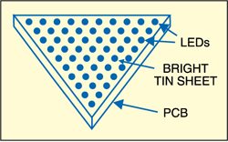
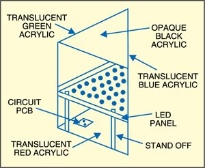
 Here are two night lamp circuits using LEDs. One could be used as a night-vision clock and the other as a TV lamp. Both the circuits are AC operated and consume very little power. These are also protected against mains fluctuations. The night-vision lamp uses twelve LEDs arranged in the circular pattern of a wall clock, while the TV lamp uses 24 LEDs in prism format.
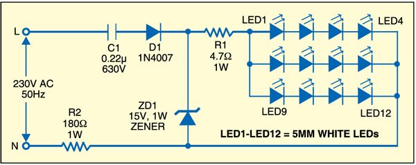
Fig.1 shows the circuit of night-vision clock. Capacitor C1 (0.22µF) reduces the current to safe limit, diode D1 provides rectified DC to bring out the characteristic colour of white LEDs and the 15V zener diode maintains the voltage at a safe level. Resistor R2 protects the circuit against high inrush current, while resistor R1 is used for additional protection of the LEDs.
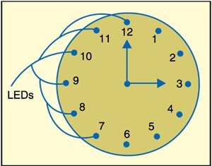
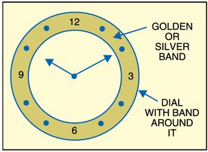
Assemble the circuit on a general-purpose PCB and mount the white LEDs (LED1 through LED12), through drilled holes, in the circular format of the clock dial as shown in Fig. 2. Similarly, you can mount LEDs on another dial of the clock as shown in Fig. 3.
Fig. 4 shows the TV lamp circuit. Watching TV in darkness puts strain on your eyes. So an illumination of 10-15W is recommended. The circuit described here is known as Ken Schultz circuit. It uses a total of 24 white LEDs (LED13 to LED36) and is well balanced against surges and voltage spikes. The lamp produces almost no heat.
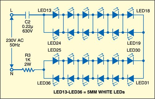
Assemble the circuit on a general-purpose PCB, with the white LEDs (LED13 through LED36) mounted in a triangular format (Fig. 5). Now enclose it in the proposed TV lamp fitting shown in Fig. 6.
