


 Most thefts happen after midnight hours when people enter the second phase of sleep called ‘paradoxical’ sleep. Here is an energy-saving night security light that causes the thieves to abort the theft attempt by lighting up the possible sites of intrusion (such as kitchen or backyard of your house) at around 1:00 am. It automatically resets in the morning.
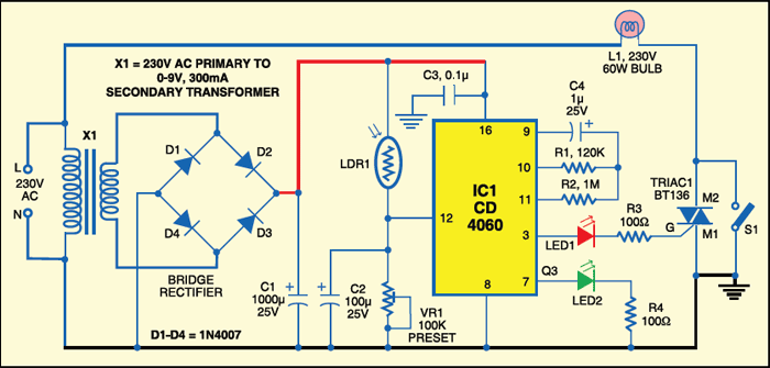
Night security light circuit
The circuit is fully automatic and uses a CMOS IC CD 4060 to get the desired time delay. Light-dependent resistor LDR1 controls reset pin 12 of IC1 for its automatic action.
Circuit operation
During day time, the low resistance of LDR1 makes pin 12 of IC1 ‘high,’ so it doesn’t oscillate. After sunset, the high resistance of LDR1 makes pin 12 of IC1 ‘low’ and it starts oscillating, which is indicated by the flashing of LED2 connected to pin 7 of IC1. The values of oscillator components (resistors R1 and R2 and capacitor C4) are chosen such that output pin 3 of IC1 goes ‘high’ after seven hours, i.e., around 1 am. This high output drives triac 1 (BT136) through LED1 and R3.

Bulb L1 connected between the phase line and M2 terminal of triac 1 turns on when the gate of triac 1 gets the trigger voltage from pin 3 of IC1. It remains ‘on’ until pin 12 of IC1 becomes high again in the morning.
Capacitors C1 and C3 act as power reserves, so IC1 keeps oscillating even if there is power interruption for a few seconds. Capacitor C2 keeps trigger pin 12 of IC1 high during day time, so slight changes in light intensity don’t affect the circuit. Using preset VR1 you can adjust the sensitivity of LDR1.

Power supply to the circuit is derived from a step-down transformer X1 (230V AC primary to 0-9V, 300mA secondary), rectified by a full-wave rectifier comprising diodes D1 through D4 and filtered by capacitor C1.
Construction & testing
Assemble the circuit on a general purpose PCB with adequate spacing between the components. Sleeve the exposed leads of the components. Using switch S1 you can turn on the lamp manually. Enclose the unit in a plastic case and mount at a location that allows adequate daylight.
Caution
Since the circuit uses 230V AC, many of its points are at AC mains voltage. It could give you lethal shock if you are not careful. So if you don’t know much about working with line voltages, do not attempt to construct this circuit. EFY will not be responsible for any kind of resulting loss or damage.
The article was first published in February 2009 and has recently been updated.
