


 Normally, sound intensity up to 30 dB is pleasant. Above 80 dB, it becomes annoying. And if it goes beyond 100 dB, it may affect your psychomotor performance, detracting your attention and causing stress. Noise pollution may also affect your hearing ability. Noise intensity level in households is around 47 dB. But hi-fi music systems and TV sets operated at high volumes add to this sound, posing a health hazard. Here’s a simple noise meter circuit that senses and displays the noise intensity level in your room. It also gives a warning beep when noise crosses the safe level of 30 dB.
Noise meter circuit
The circuit comprises a sound intensity sensor and a display unit. The regulator circuit built around regulator IC 7809 (IC1) provides regulated 9V power supply to the circuit.
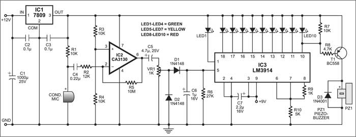
The sound intensity sensor is built around a condenser microphone, op-amp IC CA3130 (IC2) and associated components. Op-amp IC2 is configured as a high-gain inverting amplifier. The voltage supply to IC2 at its non-inverting pin 3 is divided to half by resistors R3 and R4, which is also used as the reference voltage. Resistor R1 determines the sensitivity of the condenser microphone.

Circuit operation
The microphone picks up sound vibrations and converts them into the corresponding electric pulses, which are fed to the inverting input of IC2 (pin 2) via capacitor C4 and resistor R2. Capacitor C4 block sany DC entering the op-amp, since it may affect the functioning of the op-amp. The output of IC2 is connected to the inverting input through resistor R5 (10 mega-ohms) for negative feedback. Since the input impedance of IC2 is very high, even a small current can activate the op-amp.
The output of IC2 is given to preset VR1 via capacitor C5, which is used to control the volume. Capacitor C5 blocks DC, allowing only AC to pass through preset VR1. The AC signals from the wiper of VR1 are fed to a diode pump comprising diodes Dl and D2. The diode pump rectifies the AC and maintains it at the output level of IC2. Capacitor C6 acts as a reservoir capacitor for DC and resistor R6 provides the path for its discharge.

The display circuit is built around monolithic IC LM3914 (IC3), which senses the analogue voltage and drives ten LEDs to provide a logarithmic analogue display. Current through the LEDs is regulated by the internal resistors of IC3, eliminating the need for external resistors. The built-in low-bias input buffer of IC3 accepts signals down to ground potential and drives ten individual comparators inside IC3. The outputs of IC3 go low in a descending order from 18 to 10 as the input voltage increases.
Each LED connected to the output of IC3 represents the sound level of 3 dB, so when all the ten LEDs glow, it means the sound intensity is 30 dB.
Pin 9 of IC3 is connected to 9V to get the dot-mode display. In the dot-mode display, there is a small amount of overlap between segments. This assures that at no time will all LEDs be ‘off.’
When output pin 10 of IC3 goes low, pnp transistor T1 gets base bias (normally cut-off due to resistor R7) to sound the piezobuzzer (PZ1) connected to its collector.
Construction & testing
The noise meter circuit can be constructed on any general-purpose PCB. Condenser microphone should be connected using a shield wire and enclosed in a tube to increase its sensitivity. For audiovisual indications, use a small DC piezobuzzer and transparent LEDs. Adjust preset VR1 until only the first LED (LED1) lights up. Keep the circuit near the audio equipment or TV set to monitor the audio level.
This article was orignially published in October 2004 and has been recently updated.

Sir, can I use LM3915 or LM3916 instead of LM3914?