


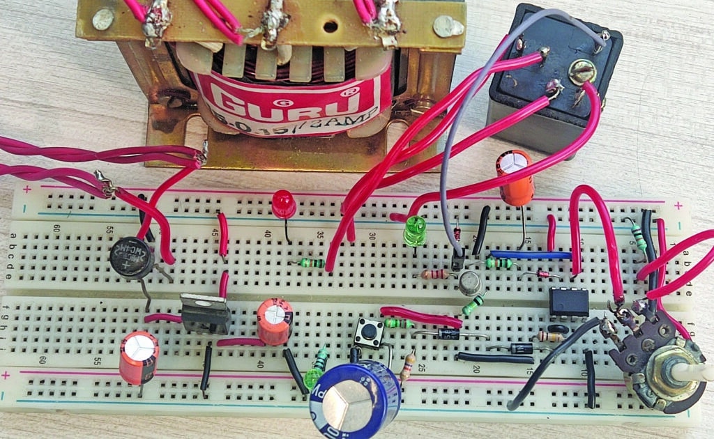
This simple on/off timer can control any household electrical device that needs to be switched on or off after a specific duration. It employs inexpensive components wired in an analogue circuit, providing extended timer duration without the complexity of digital ICs or microprocessor programming. Higher loads can be controlled by selecting higher current relays, switches, and wires, or external contactors. EFY lab tested the prototype on a breadboard, as shown in Fig. 1.
| Parts List | |
| Semiconductors: | |
| IC1 | LM7812 |
| IC2 (IC2A-IC2C) | – LM358 op-amp |
| T1 | – BC547 npn transistor |
| BR1 | – DB107, 1A bridge rectifier |
| D1 | – 1N4007 rectifier diode |
| D2 | – 1N4148 signal diode |
| ZD1 | – 2.2V zener diode |
| LED1, LED2 | – 5mm LED |
| Resistors (all 1/4-watt, ±5% carbon): | |
| R1 | – 47-kilo-ohm |
| R2 | – 2.2-mega-ohm |
| R3, R4 | – 100-kilo-ohm |
| R5, R6 | – 10-kilo-ohm |
| R7 | – 1-kilo-ohm |
| R8 | – 2.2-kilo-ohm |
| VR1 | – 100-kilo-ohm potmeter |
| Capacitors: | |
| C1, C2, C4 | – 220µF, 25V electrolytic |
| C3 | – 4700µF, 25V electrolytic |
| Miscellaneous: | |
| X1 | – 230V AC primary to 12V, 500mA secondary transformer |
| RL1 | – 12V, 10A SPDT relay |
| S1 | – Push-to-on switch |
| S2 | – 10A SPDT switch |
| CON1 | – 6A, 230V AC cord |
| CON2 | – 6A, 230V plug socket |
| Enclosure | – Suitable-size PVC enclosure |
| PCB board | – 10.2cm x 7.6cm (4”x3”) veroboard |
Demo:
DIY On/Off Timer – Circuit and Working

EFY++ CONTENT: ACCESS TO THIS CONTENT IS FREE! BUT YOU NEED TO BE A REGISTERED USER.

