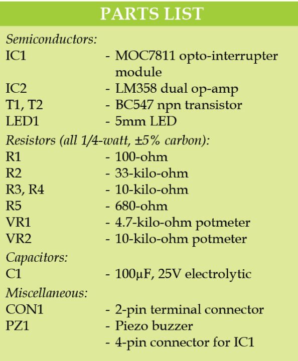
 An optical smoke alarm (also called photo-electric smoke alarm) works using the light scatter principle. The alarm contains a pulsed Infra red LED which pulses a beam of light into the sensor chamber every 10 seconds to check for smoke particles. This optical smoke alarm (Fig. 1) is built around opto-interrupter MOC7811 (IC1) and dual op-amp LM358 (IC2).
When a fire breaks out smoke will enter the optical chamber through the opening vents. When thick black smoke enters in the gap (slotted area) of the opto-interrupter sensor (IC1), its internal photo transistor stops conduction. The smoke particles cause the Infra red light to be scattered onto the photodiode light receptor. As a result, output of the dual op-amp goes low. So transistor T1 stops conduction and T2 starts conducting. This makes the piezo buzzer (PZ1) sound an alarm and LED1 to glow.
Potmeter VR1 controls the intensity of the internal LED of MOC7811. Potmeter VR2 is controls the reference voltage at pin 3 of IC2.
The circuit works off a 9V battery.

Optical smoke alarm construction and testing
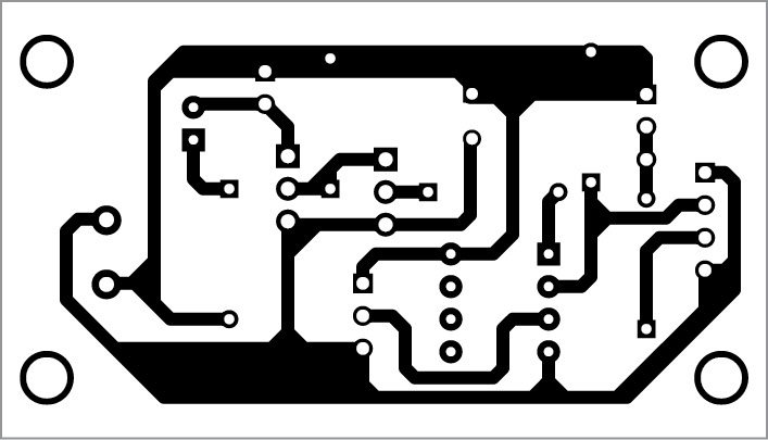
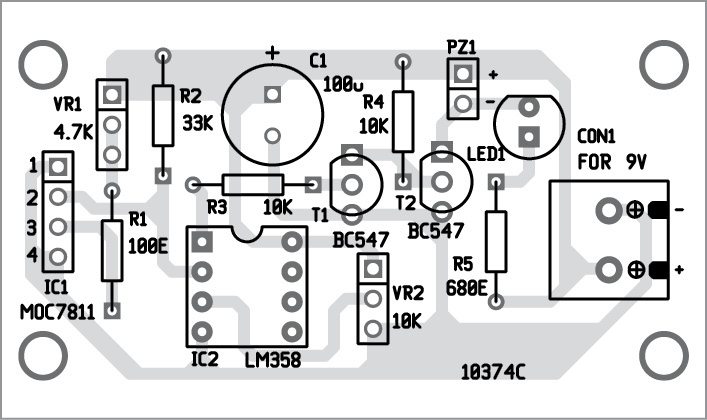
An actual-size, single-side PCB for the optical smoke alarm and its component layout is given below. After assembling the circuit on PCB, enclose it in a suitable box. Install MOC7811 at a proper location for monitoring smoke or fire. Optical technology makes the alarms less prone to false alarms from cooking fumes.


Fix CON1, LED1 and piezo buzzer on the front side of the cabinet. VR2 is used for reference setting. Connect a 9V battery to CON1.

Download PCB and Component layout PDFs: Click here
The project kit is available at grab.electronicsforu.com.


Comment:hello sir I am student of engg I choose the topic optical smoke alarm in this project I am confuse , how many sensor are use in one circuit mean when we use in application in office,house etc and in one room how many sensor we can use.
where is the sensor in this circuit
MOC7811 is the sensor for monitoring smoke/fire.
will the sensor react to less smoke or only for black thick smoke???
sir,I want to know more about the circuit.More about the circuit connections and the components.
How to check the output??
Insert a thin opaque object in the slotted area of the sensor( MOC7811), you will see the LED glow and hear the alarm sound from the buzzer.
sir , we want more information about this project …..!
Kindly elaborate your query.
Want more information about this project
Is there any specific information are you looking for?
is there any alternative for moc7811? because it is hard to find this country in my country
I mean this IC in my country
MOC7811 can be replaced with M27A1.
Sir can we use resistors having little bit different values from that actual values given in circuit?
Will it detect smoke from match box or agarbattis ?
are those the correct LM358 pinouts because they are different from the one i searched on google
Yes, it is correct. Different manufacturers follow different notations, for e.g. pin names can be IN1+ or INA+ but they are same thing.