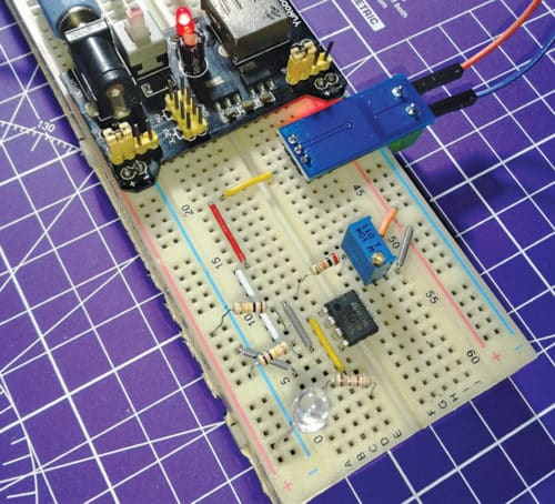
 The overcurrent fault detector presented here is a general-purpose current-consumption sensor circuit that raises an alert when the flow of current through the system exceeds a certain limit. This simple circuit is based on ACS712 Hall Effect-based linear current sensor chip. The author’s prototype is shown in Fig. 1.
Circuit and working
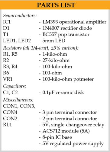
The circuit diagram of the overcurrent fault detector is shown in Fig. 2. It is built around ACS712 current sensor module, op-amp LM393 (IC1), diode 1N4007 (D1), pnp transistor BC557 (T1), 5V single-changeover relay (RL1) and a few other components.
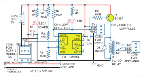
A 5A version of the ACS712 current sensor is used here. The output sensitivity of the sensor designed for 5V single-supply operation is 185mV/A, and its quiescent output voltage (output of the sensor when the primary current is zero) nominally remains at Vcc/2.
The rest of the circuit is a common comparator built around one part of the popular LM393 (IC1). Analogue output of the ACS712 module is connected to inverting input (pin 2) of IC1, while non-inverting input (pin 3) of IC1 is connected to an adjustable potential divider (VR1, R2, and R3). A pull-up resistor (R4) and an overcurrent fault indicator (LED2) are connected at the output (pin 1) of IC1. This open-collector output pin 1 goes to a low (L) level when there is an overcurrent fault condition.
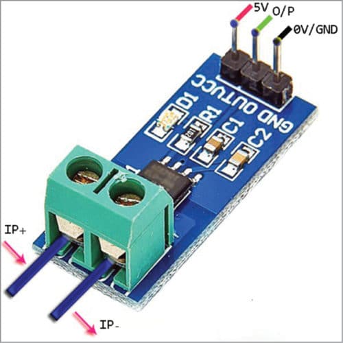
The ACS712 current sensor is available in surface mount SOIC8 package, which is often hard for some makers to handle and solder. Luckily, you can buy an expensive and compact pre-wired ACS712 module (Fig. 3) from most online component vendors. Since LM393 has an open-collector output, you can safely interface this circuit with a 5V or 3.3V microcontroller board through the CON3 connector. So, make arrangements in the circuit board to remove/add the optional output components (R4-R5-LED2) when required.
If you want to implement an add-on circuit, the easiest way is by using a simple electromagnetic relay driver circuit built around transistor T1, diode D1, and relay RL1. It can turn on appliances like annunciator (or connect/disconnect any electrical device) connected across CON4 once the current reaches a particular level.
Construction and calibration
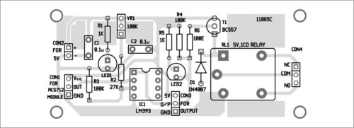
An actual-size PCB layout for the overcurrent fault detector is shown in Fig. 4 and its components layout in Fig. 5. After assembling the circuit on PCB, connect a 5V across CON2. Connect a 12V battery at IP+ and load at IP- of the ACS712 sensor module.

Download PCB and component layout PDFs: click here
The trip-point can easily be configured through the potmeter (VR1). The trip-point in the author’s prototype is set at 3A.
To set up for a particular application, you can alter the values of VR1 and R2. Assume that you need an overcurrent fault detection just above 2A. At the current of 2A, the ACS712 module roughly gives an output of 2.87V, and the same voltage should be at its inverting input pin. Therefore you should tune VR1 to set the appropriate voltage at the non-inverting input of IC1 so that it provides an overcurrent fault alert signal (logic-low) when the current level goes beyond 2A.
Note. The calibration process demands both theoretical and empirical skills. ACS712 current sensor used here can handle current up to 5A. It can convert input current into an analogue output voltage of about 2.5V plus 185mV/A. One drawback of the ACS712 sensor is that it tends to be quite unstable at lower currents. It is hypersensitive to external magnetic fields, so keep the working circuit away from strong magnetic fields.
T.K. Hareendran is an electronics designer, hardware beta tester, technical author, and product reviewer


Dear Sir,
Your project is so good. I am trying this by my students.please provide me working principle.
Thanks & Regards
Srinivasa Rao.N
Thanks for the feedback! The detail working of the project including working principle is given in the article. Please elaborate your exact requirement