


 Here’s a simple panel frequency meter to measure the frequency of 230V AC mains. When you connect it to the 230V AC line, the display shows the line frequency. Generally, the line frequency is 50 Hz, which may vary from 48 Hz to 52 Hz. Beyond this frequency range, sensitive equipment may start malfunctioning.
Frequency meter circuit
The AC mains supply is stepped down by transformer X1 to deliver a secondary output of 9V-0-9V AC, 250 mA. The secondary output of the transformer is rectified by diodes D1 and D2, filtered by capacitor C1 and given to regulator IC1 to produce regulated 6V DC. 9V AC is also connected to pins 2 and 6 of IC2 via resistor R1. Timer IC2 converts the sinewave frequency sample of AC mains into a square wave that is more suitable for the circuit operation.
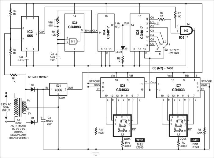
IC CD4093 (IC3) is used as an oscillator-cum-divider. The oscillator, wired around gate N1, produces 10Hz clock. Decade counter IC4 divides 10Hz clock by 10 to produce 1Hz clock. The output of gate N1 is fed back to its inputs via potentiometer VR1 and resistor R4. Capacitor C2 connected between the inputs of gate N1 and ground charges/discharges depending on the logic level at the output of gate N1. The values of VR1, R4 and C2 are selected to produce accurate 10Hz clock.

Decade counter IC CD4017 (IC4) divides the output of IC3 by 10 to provide one pulse per second. LED1 connected to pin 12 of IC4 gives one flash per second to indicate that the oscillator and the counter are working properly.
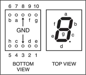
Fig. 2: Top and bottom views of LTS543 common-cathode, 7-segment displays
This 1Hz clock is fed to clock pin 14 of decade counter IC CD4017 (IC5), whose Q0 output is given to pin 2 and the square wave produced by IC2 is given to pin 1 of AND gate N1. Therefore, the unknown frequency of AC mains line, applied to pin 1 of AND gate N1, passes through it for only one second and the number of clocks per second are counted by IC7 and IC8.

Decade counters/7-segment decoders IC7 and IC8 are cascaded to drive common-cathode, 7-segment displays DIS1 and DIS2 (each LTS543). DIS1 shows units place of the frequency and DIS2 shows tens place. The top and bottom views of LTS543 common-cathode, 7-segment displays are shown in Fig. 2.
Circuit operation
This is an auto-reset circuit. You can select the reset time of 1 second through 5 seconds using rotary switch S2, which is connected to reset pins of IC5, IC7 and IC8. For long-time display of the frequency, keep the knob of rotary switch S2 towards fifth position. Keeping rotary switch S2 to first position (minimum reset time) allows you to instantly see any variation in the supply frequency on the display. Also, while adjusting the generator frequency to mains frequency, keep rotary switch S2 towards first position.
For more circuit articles: click here
The article was first published in June 2004 and has recently been updated.

Hi. I confused completely about N1 & N2. IS there any relation between N1 and N2 or not? If yes, why they are defined with different IC,s (4093 and 7408)? If not, why they defined with N1 and N2?? As a rule Both of them should be defined with N1. Please help me.
Thanks a lot.
I need panel frequency meter project
Hi Huzaifa, you can find all the information regarding the same within the article.