 Oscilloscopes are an essential tool for electronics hobbyists and professionals to verify that their designs would work as expected. PC based Oscilloscope score over standalone oscilloscopes due to their compact size, low cost and ability to do offline analysis.
Here we describe how you can make your own oscilloscope at a very low cost using your PC and an Arduino board as the hardware for signal acquisition. You can use this oscilloscope to capture frequency signals up to 5kHz. The Arduino board, the heart of the oscilloscope, reads the values from its inbuilt analogue-to-digital converter (ADC) and pushes these to the PC via USB port. We have provided here an Arduino sketch, which you can compile and load directly to the Arduino. You also need to install an executable file or application in your Windows PC. This application works as the front-end to plot input signals as waveforms on your computer screen.
The Arduino board consists of Atmel’s AVR microcontroller, which can be 8-, 16- or 32-bit based on the type of the board. For this project, you can use any variant of the Arduino as hardware. The AVR microcontroller has an inbuilt ADC. In the project, we use pin A0 to capture the input signal. The captured input signal is fed to UART via UART-USB converter in the Arduino to the PC. A virtual COM port is created by Windows whenever the Arduino connects to the PC. A Windows-based application developed using NI LabWindows opens up the virtual COM port and starts plotting signals visually using Graph libraries.
The sampling speed of the oscilloscope is limited by the baud rate of the UART. The Arduino sketch is coded to read the ADC using ISR, and the UART baud rate is configured at 115200, which sends data at 85µs intervals. This gives an effective sampling rate of 12kSa/s.
Construction
The PC scope set-up is quite simple and straightforward as shown in Fig. 1. The Arduino board connects to your laptop or PC via the USB cable. Any external power supply for the board is not required as the board is powered by the USB only. Connect switching diodes (D1 and D2) as input protection circuit to pin A0 of the Arduino’s ADC. You need Arduino sketch (pcscope.ino) and PC software or executable file (PCScope.exe) in order to use this circuit. Install PCScope.exe program (developed by author) in your Windows PC and open the application. Next, open the Arduino sketch from Arduino IDE and compile the sketch. Connect the Arduino board to the PC and flash the sketch into the microcontroller on the Arduino board.
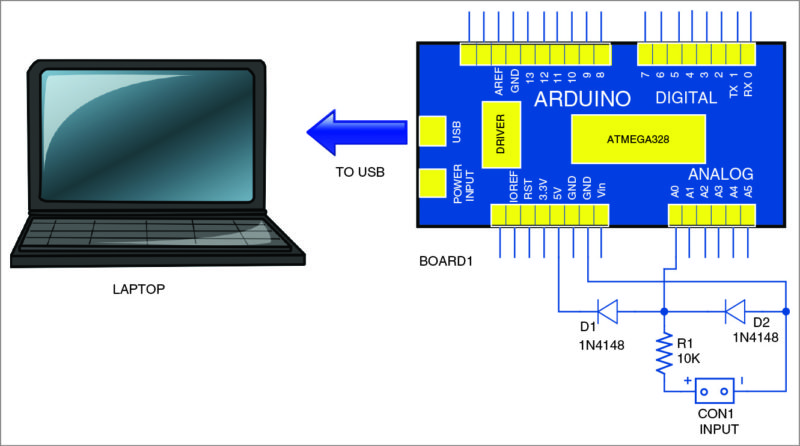
The ADC of Arduino can measure voltages up to 5V. So it is advisable to add a small protection circuit to limit the input voltage to 5V and clamp the negative voltage. A low-power, fast-switching diode like 1N4148 can be used to protect the input pin. Connect a 10-kilo-ohm resistor in series with the input. It will work as a current limiter in case the input goes beyond 5V. Additional voltage dividers can be used in case you need to measure voltages higher than 5V.
Software
Arduino sketch. The sampling rate of this PC scope application is limited by the rate at which the data is sent to the PC. Baud rate of 115000 gives time interval of around 85 µs. It is important to get the ADC signals much before this time to get reliable data plotting. The sketch reads pin A0 of Board1 and sends to UART at 115200 baud rate. At this speed, bytes of the input are pushed at time intervals of around 85µs.
By default, the ADC configuration of the Arduino gives samples every 116µs. So here the ADC is configured with additional lines of code to get samples faster than 85µs by setting the prescaler to 16. With this, you get ADC conversion every 20µs, which is much faster than the UART data transfer rate.
Download source Folder
PC software. As stated earlier, the front-end PC software for signal acquisition and processing is developed using NI LabWindows. The serial port data is captured through Arduino at regular time intervals and plotted as a graph on the screen using the Plot function library. The display points along X-axis are calculated based on the user-defined time scale. The Y-axis range is set using the voltage selection control.
Testing
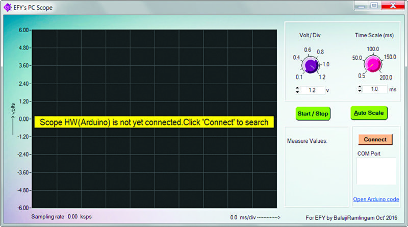
After installing the PC scope application, click ‘Connect’ button on your PC screen to connect to the Arduino board (Fig. 2). When the board gets connected to your PC, you will get a confirmation message for three seconds as shown in Fig. 3.
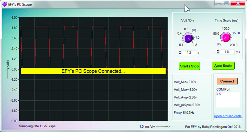
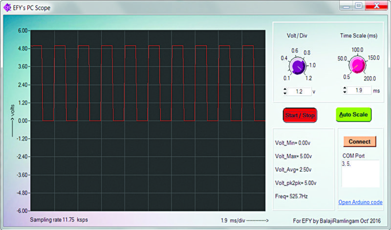
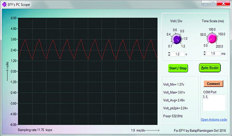
Feed any squarewave input of up to 5kHz at CON1. The software must plot its output waveform on your PC. Square and triangular output waveforms of 525Hz and 530Hz captured on the screen during testing are shown in Figs 4 and 5, respectively. Similarly, you can feed rectangular or pulse inputs (but not sine waves) to get output waveforms.
Feel interested? Check out more electronics projects.


What is the use of this file “PCScope.001”?
Actually, it is the PC software file mentioned in the article. You need to provide the password to open it. Password is 1234.
Where can i download the software? The link provided is broken .
Hi Iman, Please refresh the page. I have checked the link. It is working fine.
why we can use upto 5khz only?
how can we increase the frequency like 1M or up
The reply from author Ramalingam Balaji.
“With Arduino Uno, the given ADC sampling with good signal stability, 1M samples will not be possible. We need to look for a DSP solution with fast ADC for 1M sample and more.”
I need full detail in construction
Please elaborate your exact requirement
Hello,
I think there is PC soundcard oscilloscope project it’s better than such staff and it capturs more than 5Khz and costs low maybe with arduino you have to develope fast oscilloscope
Thank you
The reply from author Ramalingam Balaji.
“In Arduino, we can make more than two channels but in sound card that’s not possible. Arduino scope can be used with standalone display if we further extend the project with Display. Not possible in sound card.
With SD card interface, you can log into Arduino scope… There are lot of benefits on scalable solution with Arduino.”
Hi, do you need to download NI Lab Windows in order to use “PCscope.002” or do we just run this on the command prompt?
Actually you don’t need to use PCscope.002. Just run the Setup file to install PCscope application. Everything will be taken care of by the software.
PCScope won’t run because I’m missing cvirt.dll. Would reinstalling fix this problem or do I have to get it from an external source? Thanks!
I have used arduino nano in stead of arduino uno but there are unexpected noise curves on the screen in no signal condition. but whenever a known frequency is made to be appeared in to it’s input then the real curve is shown on the screen.
Here’s the reply received from author Ramalingam Balaji: Connect 100kOhm to the ADC pin and ground. This will suppress the noise when the pin is unconnected.
can we save the data shown in the scope?
You can take screenshots of the waveform data and save in your computer.
Hello, does a trigger function exist or wold it be easy to implement?
How do I download pcscope.exe
can use Arduino nano instead of uno?
It’s a great solution, you are very clever.
bugs:
– Frequency does not always appear correctly
– there is no trigger in the application to automatically stop the image
Thanks for app, possibly new version
I could not install the PC Scope in my laptop with Win 10. The software is asking the insert a disc in Drive C.
I ran into this same problem, but was able to get PCscope to install by extacting & moving the rar/zip file out of the downloads directory and then installing it.
Can anyone modifications which will allow measuring voltages from -5V to 5V instead of 0V to 5V?
nice work, im impressed but why cant we display sine wave and what modifications if any to make it display sine wave
Can we use this to measure output power of Audio Amplifier ics like tda2030A ?
what is con1 in this project?
and can you tell me where to buy this??????
Thank you works well and I also added 2 attenuators to the circuit with different test lead sockets, works perfect it dose need a trigger and way of adjusting voltage zero location on display
Is it possible to connet this PC-software like ….
STM32Necleo_L476RG (UART) > UART-USB converter > NetBook
The software is well installed and I got the EFY’s PC Scope window. And COM port 5 is assigned but the window shows “Unable to find HW. Click “Connect’ to search again”
Is there any comments?
Hi,Efy ,whether i can get source code of software (pc oscilloscope),waiting for ur valuable Reply.
The Source Code is present at the end of the article.
You’re wrong. Check it. There is no source code for the PC application, only the installer. The source code in the RAR is the sketch for Arduino.
Hi, thanks for the program. It ran first time on my Arduino Uno and PCScope running on a Ubuntu Linux PC. Well done.
You are most welcome.
this is great! but can i use it to measure pulsating dc signal from full bridge rectifier? anyway, thanks for sharing!
Reply from author Ramalingam Balaji : Yes. Pulsating DC signal can be measured as long as the ground of rectifier does no go negative with respect to Arduino ground.
hi when i want to uplode the code this error (‘ADCSRA’ was not declared in this scope) is shown
what should i do for it?
Do you have version of pcscope for mac?
No, not for Mac, sorry
Can you share Lab Windows source file please
Please download it from the link given in the article above.
Good day sir! Can I use this project with my project for a contest? Is it enough to mention your names and this article in my citations? Thank you so much for your response.
Yes, you can use it.
Thank you Sir.
You are welcome.
Can I store the readings as a data in .txt or.csv format.
Hi,is there a way to open the source code to change add some features? I can’t seen to find a way to open PCScope.001 and .002 on LabWindows. I want to add a period display and more control over the graph,but I can’t open those files
How can I edit the source code to add more functions in LabWindows?
Hi all. This looks great, but unfortunately I can’t get PC Scope to connect to the Arduino. Keeps telling me to try to connect again. Any hints?
When you connect the Arduino board to PC/Laptop, select the correct COM port followed by clicking on “Connect” button in PC Scope software
Wow
What a amazing little tool. It worked great. I tried adding more resistance to change the voltage reading but I’m still getting the exact same reading. So I’m a little dumbfounded. Shouldn’t changing to 15K ohm drop the voltage?
Link del software y codigo estan caidos, pudieran compartir de nuevo
Link del software y codigo estan caidos, pudieran compartir de nuevo
Looks like the software can’t find the com port the arduino is connected to. The Arduino IDE does identify the port.
Not sure how to solve this.
Is there a way to cleanly remove the pcscope program — it doesn’t show up in the add/remove program list.
thanks,
Dan