


 Here is a PC driven LED display circuit to generate sequentially running light effects using a simple program written in C. The output of the program is taken from the LPT port of a PC and then fed to the interfacing circuit for the LED display. The outputs of the interfacing circuit are decoded, inverted, and then connected to LEDs through optocouplers.
PC Driven LED Display
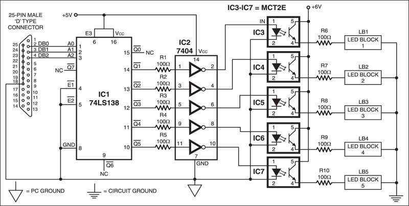
The interfacing circuit along with the 25-pin parallel port is shown in Fig. 1. IC1 (74LS138) is a high-speed 1-of-8 decoder/demultiplexer. In the circuit, only five outputs (pins 10 through 14) of IC1 are used. These outputs are inverted using NOT gate IC2 (7404). Optocouplers IC3 through IC7 (MCT2E) are used to prevent the circuit from damage in the event of short circuit in the load. Thus the loads comprising LED blocks LB1 through LB5 are isolated from the interfacing circuit including the PC. Each LED block contains a number of LEDs connected in series.
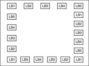
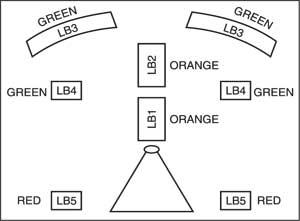
The LEDs can be arranged, for instance, to display a sequential running light and fountain pot as shown in Figs 2 and 3. The colour of LED blocks can be green and red alternately.

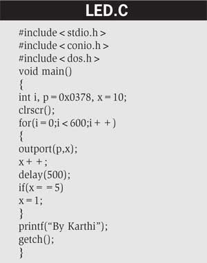
The program can be compiled and run through Turbo C compiler. In the program, the function outport(p,x) is used, where ‘p’ is the address of the controller port and ‘x’ is the value sent to it. Here, controller port LPT1 is used, whose base address is 378H. If LPT2 is to be used, the base address must be 278H. When the delay time delay() is increased, the running speed of LEDs decreases and vice versa.
In the circuit, 100-ohm fixed resistors R6 through R10 can be replaced with 100-ohm or 200-ohm presets for decreasing and increasing the intensity of LEDs.

The program for LED display is as follows:
The article was first published in July 2003 and has recently been updated.
