Electrical appliances like refrigerators and air-conditioners consume heavy current if the line voltage drops during the peak hours between 6 pm and 9 pm. If there is no low-voltage cut-off in these appliances, it will cause wastage of current and heating of the appliances. Over-heating may, in turn, reduce the efficiency of the compressors of these appliances.
This circuit proves useful here in that it automatically turns an appliance off during the peak hours. After three hours, the appliance will turn on again.
An LDR-based switch is used for automatic switching off of power to the circuit. During daytime, LDR1 offers low resistance, so transistor T1 forward biases to pull its collector voltage to the ground and inhibit T2 from forward biasing. In this state, the remaining circuit is switched off and power to the appliance is obtained from the normally-closed (N/C) contacts of relay RL1.

When the daylight reduces around 6 pm, LDR1 offers increased resistance and transistor T1 is cut off. Then transistor T2 provides power to the circuit. Using preset VR1, you can adjust the sensitivity of LDR1 for the desired light level.
The timer circuit is designed using the 14-stage ripple counter CD4060 (IC1) to give 3-hour timing by taking pin 1 (Q11) as the output. When IC1 gets power from transistor T2, it resets through C1 and R3 and starts oscillating. Reservoir capacitor C2 maintains the voltage to IC1 stable so that the oscillation is not affected by slight variations in the power supply. Resistor R4 along with capacitor C3 maintains the oscillation of IC1, as indicated by the blinking of LED1 connected to its output pin 7 (Q3).

The timeout period of the timer can be calculated using the relationship:
T = 2n/fosc in seconds
where ‘n’ is the selected output number and fosc = 1/2.3(R4.C3)
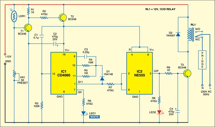
Resistor R4 is connected to pin 10 and capacitor C3 is connected to pin 9 of IC1. When Q11 output becomes high, diode D1 inhibits further oscillation of IC1. Q11 output remains high until IC1 resets in the morning.
IC2 is a bistable latch using timer NE555. Its trigger input pin 2 and threshold input pin 6 are tied together so that at power-on, the output of IC2 goes high and latches since its trigger and threshold inputs are floating. Relay driver transistor T3 conducts to energise relay RL1 and the appliance, say, refrigerator, is disconnected from mains. This condition persists for three hours during the peak hours.
After the timeout period of IC1, its Q11 pin goes high to send a positive pulse to the threshold input of IC2 through resistor R7. This high-going pulse resets IC2 and its output becomes low. Transistor T3 cuts off and relay RL1 de-energises to turn the appliance ‘on’ through N/C contacts of relay RL1. Capacitor C4 maintains the base current of transistor T3 for clean switching and avoiding chattering of the relay. Freewheeling diode D2 removes back emf of the relay.
Assemble the circuit on any general-purpose PCB and enclose in a suitable cabinet. Relay contacts should have a current rating that is sufficient to handle the load. Use wires of proper guage for connecting the relay contacts to AC mains wire. Earth properly and use a three-pin socket to take AC from the unit. Fix the unit at a place where sufficient daylight illuminates the LDR.