


 Telephone ringing all of a sudden in the middle of a serious meeting is quite irritating. The automatic bell silencer circuit described here is the answer to this problem. By pressing a switch, you can make your phone silent for a preset time (here, 12 minutes). When this time period is over, the telephone will automatically revert to its normal mode. Anyone who makes a call during the silent period will get a busy tone.
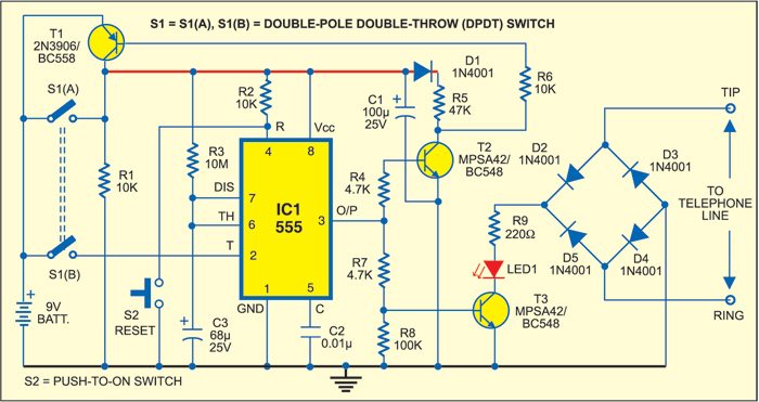
As shown in Fig. 1, the circuit is built around popular timer IC 555 (IC1), which is wired in monostable mode. The circuit is triggered by double-pole double-throw (DPDT) switch S1. Pressing this spring-loaded switch S1 provides 9V battery supply to IC1 to enable the circuit. Since switch S1(A) is connected across the collector and emitter of pnp transistor T1, 9V power supply of IC1 is maintained even if S1 is released. This supply for IC1 remains high for the time period of IC1 decided by the combination of resistor R3 and capacitor C3.
Pressing S1 also triggers IC1. The output of IC1 at pin 3 goes high for around 12 minutes. You can increase/ decrease this time by increasing/de-creasing the values of R3 and C3.

The output voltage of IC1 is fed to the base of npn transistors T2 and T3 through current-limiting resistors R4 and R7, respectively. The collector of transistor T3 is connected to the telephone line through LED1, resistor R9 and bridge rectifier comprising diodes D2 through D5. When transistor T3 con-ducts, LED1 glows and the telephone line becomes busy. LED1 provides an indication that the silencer is enabled.
As soon as the time period of IC1 (12 minutes) is over, the output of IC1 at pin 3 goes low. All the transistors cut off, shutting off power supply to the entire circuit and disabling it. When transistor T3 cuts off, resistor R9 is removed from the telephone line, placing the telephone line in normal operation. Reset switch S2 is used to make the telephone line available again at any time.

The circuit is powered by a 9V battery. Working of the circuit is simple. Connect the telephone line and the 9V battery to the circuit. Press switch S1 momentarily. LED1 glows and your telephone line becomes busy for the preset time. After the time period of IC1 is over, LED1 turns off and your telephone line becomes normal as usual.
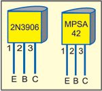
Fig. 2 shows the pin configurations of transistors 2N3906 and MPSA42.
Assemble the circuit on a general-purpose PCB and enclose in a small suitable cabinet. Fix push-to-on DPDT switch S1 either on the front side or on top of the cabinet. Connect a two-pin connector on the rear side of the cabinet for connecting the telephone lines. Fix LED1 on the front panel of the cabinet. Enclose the battery inside the cabinet. A standard 230V AC to 9V DC mains adaptor can be used in place of the 9V battery.
