This ultra-sensitive photodiode based fire detector protects your electronic devices like computer and television set. It uses a photodiode as the fire sensor and sounds an alarm immediately on sensing a spark or fire in the power supply section of the instrument and instantly cuts off the power supply. The circuit exploits the photovoltaic property of the photodiodes to sense a fire.
Photodiode Based Fire Detector Circuit
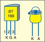
Fig. 1 shows the circuit of the fire sensor, while Fig. 2 shows pin configurations of SCR BT169 and photodiode.

The photodiode used in infrared detectors generate a photo voltage proportional to the incident light rays or infrared rays falling on it. Typically, 1V is produced in the photodiode when it is forward biased by accepting the photons. Here the passive infrared rays from the spark or fire are used to activate the photodiode to generate the photo voltage.

Since the photo voltage is very small, an extremely sensitive voltage amplifier is needed to activate the remaining part of the circuit. Here dual op-amp IC 741 (IC1) is used as a Schmitt trigger with hysteresis. It converts the input voltage signals from the photodiode into a shaped output signal. Resistors R1 and R2 form a potential divider to give half the supply voltage (4.5 volts) to the inverting input (pin 2) of IC1. Resistor R3 connects the output of IC1 to its inverting input.
The photodiode is connected between the junction of the R1-R2 divider and the non-inverting input (pin 3) of IC1. In the standby mode (in dark), the voltage across the photodiode will be zero and the output of IC1 remains low. When a spark or fire breaks out, the photodiode conducts and the output of IC1 becomes high. The hysteresis of the Schmitt trigger makes it a very sensitive amplifier. The output of IC1 remains high for a few seconds even after the photodiode becomes non-conducting. When the output becomes high, any slight change in voltage at the inverting input has no effect. This is highly useful to activate the alarm even with a single spark.

Circuit operation
The high output from IC1 is used to trigger SCR BT169 (SCR1) for activating the relay. When the relay energises, power to the device will cut off immediately. SCR1 remains latched until push-to-off switch S1 is pressed. When SCR1 conducts, T1 gets base bias and it conducts to activate alarm generator UM3561 (IC2). Zener diode ZD1 keeps the supply voltage for IC2 at a safer level of 3.1 volts. IC2 is wired to generate a fire brigade alarm by connecting its pin 6 to ground. The output of IC2 is amplified by transistor T2 to sound the alarm from the speaker.
Construction & testing
The photodiode based fire detector circuit can be easily assembled on a perfboard. It can be powered by regulated 12V DC. Connect the 230V mains supply wire to the device through the normally-closed (N/C) contacts of relay RL1. Connect the photodiode using a single-core, shielded wire and place near the power supply unit. To avoid false triggering of the circuit, keep the photodiode at a place where direct light is minimal.
The article was first published in November 2006 and has recently been updated.