


 In electronics, there are many ways to play with light the way you dream. If you are looking for an inexpensive solution, regular light-dependent resistors (LDR) can also be used as optical sensors.
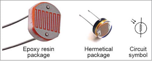
Light-dependent resistors based on cadmium-sulphide (CdS) have a resistance that varies inversely with the amount of light falling on them. These LDRs are known by many names, including photoresistor, photoconductive cell or simply the photocell. Usually, LDRs are available in epoxy resin and hermetical packages (Fig. 1).
You can take a few measurements to determine the mathematical relationship between the LDR’s resistance and lux values by following the steps given below:

- Insert the LDR into a breadboard so that the flat top of the LDR is parallel to the ground plane
- Connect your digital multimeter (with its knob turned to the resistance range) to the two leads of the LDR
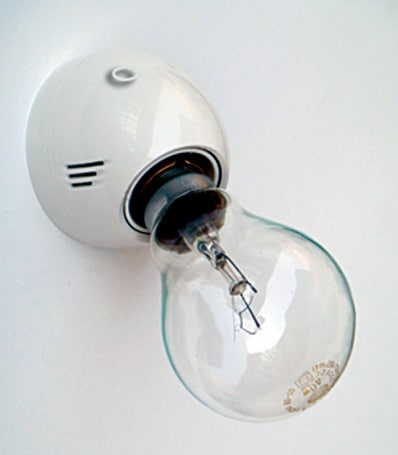
- Place the sensor of the lux meter (Fig. 2) near the LDR

4. While ensuring that the same amount of light falls on the LDR and sensor, note down the LDR’s resistance and lux values in lux meter. Repeat this process for several different light and lux levels ranging from very dark to very bright light
5. Finally, transfer your findings to a spreadsheet and plot resistance as a function of light. Typically, the graph of LDR resistance as a function of light looks as shown in Fig. 3
CdS LDRs exhibit sensitivity curves that closely match the sensitivity of the human eye, which makes them useful in applications involving human light perception, such as headlight dimmers and intensity adjustments on information displays.


LDR as a potential divider
Since the resistance of LDRs varies in response to light, usually potential divider concept is used to get a valid output for further processing by other parts of the circuit (for example, analogue-to-digital controller of a microcontroller). As shown in Fig. 4, when the LDR is at the top, we get a large Vo as the sensor has a low resistance, and when the LDR is at the bottom, we get a small Vo as the sensor has a high resistance.

Practical application of LDR: smart bulb holder
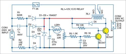
Smart bulb holder is nothing but an AC-mains-operated incandescent, compact fluorescent or LED light bulb holder with a simple dusk-to-dawn/twilight controller circuit for automatic switching of your outdoor/corridor electric light bulbs (Fig. 5). The circuit, as shown in Fig. 6, can be enclosed in an appropriate light bulb holder. It comprises two equally important parts: 12V DC low-current power supply and LDR-based twilight-controlled switching circuitry.
For the sake of simplicity, a capacitive potential divider circuit is used for the power supply. Rest of the circuit, as stated, is the ambient-light-controlled electromagnetic relay driver built around a standard photoresistor (LDR1) and two small general-purpose switching transistors T1 and T2.
In the circuit, 230V AC mains input is rectified by diodes D1 through D4 and limited by Zener diode ZD1 to 12V DC, then smoothed by capacitor C2. A 5mm photoresistor (LDR1) is used to detect the ambient light level.
When there is little or no light, the resistance of LDR1 is high. So the voltage on the base of T1 is very low, which drives the transistor into cut-off mode. Consequently, T2 conducts to energise relay RL1 and switch on the exterior light connected at CON2.
When sufficient light falls on the LDR1, the high voltage on base of T1 drives it into conduction. This interrupts the base current to T2, with the result that the relay de-energises. The switching level can be adjusted with the help of potentiometer VR1. Capacitor C3 provides a bit of hysteresis to prevent the system from jittering near the threshold level.
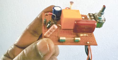
Since the circuit is connected directly to the AC mains power lines, house it inside an insulated cabinet made from wood/acrylic sheets. Make sure the relay is low-current type (well below 35 milliamperes). The author used a 12V, 400-ohm relay for the prototype (shown in Fig. 7).
This circuit is suitable for wall-mounting and/or pole installation. Connect 230V AC input to CON1 and take output from CON2 terminals.
Caution! This circuit works on 230V AC mains, so take care to avoid lethal shock.
This article is a part of the Top 10 LDR-based Electronics Projects. If you want to read more projects based on LDRs can go through this article.
To read the top 10 LDR Projects: click here


how is it possible to give 230v to small components directly