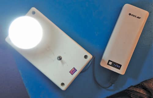
 This portable emergency light is based on a DC-to-DC booster module and a power bank. The emergency light is designed to provide sufficient illumination in case of mains power failure. Generally, a sealed lead-acid battery is used for an emergency light.
Some advantages of this portable emergency light are:
- Compactness
- Lithium-ion battery, which contains fewer toxic metals compared to other types of batteries, which may contain lead or cadmium
- Charging lifecycle of lithium-ion battery, which is more than that of a maintenance-free battery
The author’s prototype of the portable emergency light using a power bank is shown in Fig. 1.

Circuit and working
The circuit diagram of the portable emergency light is shown in Fig. 2.

In this circuit, one USB output port of the power bank is used. Output port has 5V(+V) and GND(-V) terminals.
The DC bulb gives sufficient illumination at 12V. So, boost or step up the voltage from 5V to 12V using a suitable boost converter circuit. The boost converter module should be connected between the USB and the DC bulb (B1), as shown in Fig. 2.
Main components of this emergency light are power bank, voltage boost converter, LED lamp or bulb, power on/off switch and USB A-type connector.
Power bank
A power bank is used as the main source for this circuit. Power banks are popular for charging smartphones and other devices. These have rechargeable lithium-ion or lithium-polymer batteries installed on a control circuitry on the PCB, which is enclosed in a protective casing.
Booster module
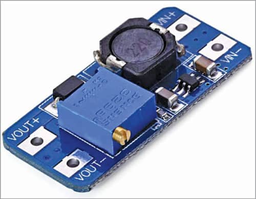
A boost converter is a DC-to-DC converter with an output voltage greater than source (input) voltage, and output current lower than source current. Here, an MT3608-based converter module is used (Fig. 3).

It boosts the voltage up to 28V, and its current rating is 2A. In this circuit, boost converter output is adjusted to 12V.
Bulb
A 5W, 12V LED bulb is used in the prototype. However, any other DC bulb or 5W LED lamp can be used.
Switch
A power on/off switch (S1) is used to provide power to the emergency lamp.
Construction and testing
After assembling the circuit, enclose it in a suitable plastic case. For testing, connect the power bank to the booster module through the USB connector and then turn on the bulb using S1.
Capacity of the power bank used in the prototype is 15,600mAh, and its charging time is around 15 hours. Charging and load enable times are variable and depend on capacity of the power bank. A fully-charged power bank can drive the bulb/load for around five hours.
Vinay Kumar K. is an instructor in E&E engineering department, NIE Institute of Technology, Koorgalli, Mysuru


Can I receive the resource package of report in Word in order to carry out his project.
I am using DC to DC booster module using 2596 ic ,after connecting with load (12 v led strip 6 leds)board got heat after few minutes and shutdown light,and board got failed,,actually what is the issue?
me to face same problem on may 2020,But i dont know the Reason
It could be shortcircuit in some components in your LED board