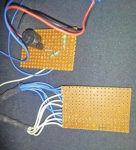
 This is a simple portable rain and steam detector in one circuit. It is compact in size, runs on 9V battery and is easy to assemble.
Circuit and working
The circuit diagram of the portable rain and steam detector is shown in Fig. 2. It is built around transistor T1, piezo buzzer PZ1, 9V battery and a few other components. Sensor-connecting terminals are marked as P1 and P2 in the circuit.


When there is no rain or steam, impedance between P1 and P2 is high. Hence, T1 does not conduct. When sensor detects rain, impedance between P1 and P2 is low. T1 gets base current via resistor R1. T1 conducts and switches on PZ1, indicating that rain or steam is detected.
To stop buzzer sound, wipe out the water or steam from the surface of the sensor. Use of power on/off switch is optional in the circuit because current drain is negligible or nil when there is no rain or steam.
Construction and testing
Assemble the components as per the circuit diagram on a breadboard or veroboard. Connect 9V battery (6F22) for the power supply. You can assemble this unit in a suitable plastic box, too. Fix the circuit and battery inside the box.
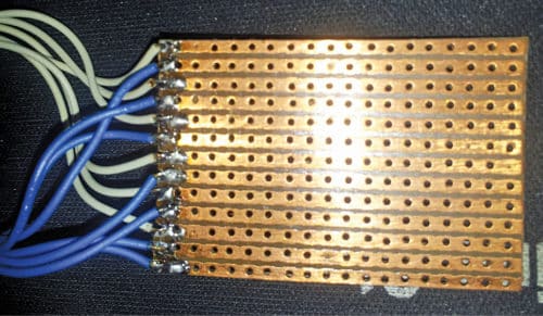
Construction of the sensor is shown in Fig. 3. The rain and steam sensor is made of a general-purpose PCB or veroboard. A 3.8cm x 5cm veroboard having thirteen tracks is used as the rain sensor.

Take seven conducting wires (say, white) and solder these on alternate copper tracks of the Veroboard, as shown in Fig. 3. Join the other ends of seven white wires, connect the joint to a suitable cable and extend it to P1.

Take another six wires (say, blue) and solder these on the veroboard on remaining alternate tracks. Similarly, join the six wires and extend it to P2 using another cable. You can use two-to-three-metre shielded cables for connecting the rain sensor to the circuit. Keep the sensor outside at a suitable location for rain detection.
P.V. Vinod Kumar is an electronics hobbyist.


This project is very important because it helps to make rain detector using few components
Thanks for the feedback!