


 This low-cost portable spectrum analyser can be used to analyse the frequency content of input signals up to 5kHz. Frequency spectrum of an input signal possesses vital information, and the same has been employed for various applications ranging from engineering to biomedical, such as speech recognition, electrocardiogram (ECG) signal analysis, fault diagnosis of induction motors, music analysis and so on.
Analysing the spectra of electrical signals provides information about dominant frequency, power, distortion, harmonics, bandwidth and other spectral components, which are not easily detectable in time-domain waveforms. Spectrum analysers are quite expensive and might not be affordable for individuals such as students and electronics hobbyists.
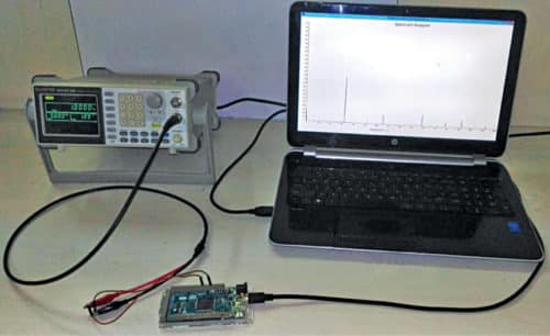
The block diagram of the proposed low-cost portable spectrum analyser is shown in Fig. 1. Snapshot of the authors’ prototype using Arduino DUE board and test setup used for evaluation is shown in Fig. 2.
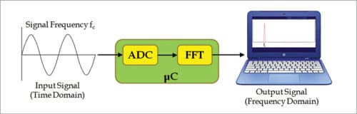
The system employs Fast Fourier Transform (FFT)-based frequency analysis. FFT is a computationally efficient algorithm for computing Discrete Fourier Transform (DFT) of sample sizes that are positive integer powers of two.
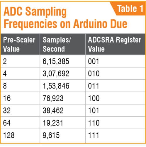
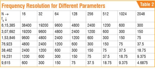
Table 1 lists the possible sampling frequencies available with Arduino Due board. These frequencies are selected using a pre-scaler value in ADCSRA register of an on-board analogue-to-digital converter (ADC). Resolution of the frequencies can be increased by either reducing the sampling frequency (fs) or by increasing the number of FFT points (N). Based on frequency resolution requirements of an application, suitable values can be selected by the designers. Table II lists the frequency resolutions for different combinations of N and fs.

A function generator is used to evaluate a system by providing input signals at different frequencies and monitoring the variation in the frequency spectrum on the laptop. An input signal is given to one of the ADC channels available onboard. Arduino FFT library is used for Arduino Due board.
Processing code to view the frequency spectrum plot on the laptop has been designed using Processing software. Source program (FFT_acc_Vs_k.pde) written in Processing can be modified as per requirement.
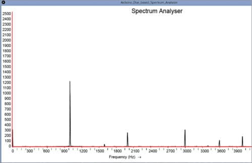
Snapshots of the output screen for input signals with 1kHz and 2kHz are shown in Figs 3 and 4, respectively, using a 2048-point FFT with fs=9615 Hz.

This project can be easily extended for multi-channel spectrum analysis, as Arduino Due has twelve analogue input channels.
Testing steps
The steps for testing are given below.
1. Download and install Arduino IDE from this website, and Processing software from this website.
2. Connect Arduino DUE board with the laptop using USB cable and open Arduino IDE. Add SplitRadixRealP library under libraries folder of the IDE. Open Arduino code (FFT_Split_for_GUI.ino) using Arduino IDE software. Under Tools, select Arduino Due (Programming port) board and COM port. Next, compile and upload the source code to Arduino DUE board.
3. Open Processing source code (FFT_acc_Vs_k.pde) using Processing software. Change COM port in the source code.
4. Connect input from a function generator to Arduino Due pin A1. Make sure that ground is common and run the program/sketch. Output spectrum window will open and show the spectrum for the given input signal.
5. You can view the spectrum in the given range on x-axis, while y-axis shows amplitude of the input signal given at A1 pin of Arduino Due board.
Download source folder: click here
Also, check the diy audio spectrum analyzer.
Akash Vakil served as research assistant at Crucible of Research and Innovation (CORI), PES University, and is currently pursuing master’s at Arizona State University, Tempe, Arizona
Dr J. Manikandan is professor at CORI, and heads the VLSI and embedded systems domain of ECE department at PES University, Bengaluru

Really informative and useful for me
Thanks for posting
You are most welcome.
Hello, first of all; excellent work. I have problems compiling the code in Arduino, all troubles have an associated error of “PIOB was not declared in this scope”. Any idea why I have this error? Thank you
Not able to open the source code! any idea why?
Kindly refresh the page and redownload.
Kindly refresh the page and redownload the Source Code.
download is not working it says …
Site unavailable. Please contact hosting support for more details.
i am unable to find ino code
Hi, we were facing some issues earlier with the Source page. Kindly refresh the page and retry.