


 The low voltage protector circuit described here protects your electrical appliances like AC motors from damage due to low voltage at power-on. It remains standby without giving power to the load after power resumes. The load can be switched on only manually. This prevents damage to the device if it is ‘ON’ when power resumes.
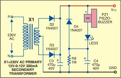
The unregulated power supply is derived from a 12V-0-12V, 300mA step-down transformer and rectifying diodes D2 and D3. The rectified DC is made ripple-free using capacitor C3. An audio/video indicator (piezobuzzer and LED3) is provided along with the power supply for power resumption.
When power is switched on, capacitor C4 charges through the piezobuzzer and LED3, making both of them active. The piezobuzzer beeps and LED3 glows for a few seconds. When capacitor C4 is fully charged, the cathode of the LED becomes high inhibiting further flow of current through the buzzer.
When the power is off, capacitor C4 discharges through resistor R9.

Low voltage protector circuit
The circuit uses IC CA3140 (IC1) as a voltage comparator to detect voltage changes in the unregulated power supply due to AC mains. Mains voltage changes in the primary as also the secondary winding of the transformer, which is sensed by IC1 to energise/de-energise the relay. Zener diode ZD1 provides a reference voltage of 3V to make transistor T1 conduct. Preset VR1 adjusts the breakdown point of ZD1.
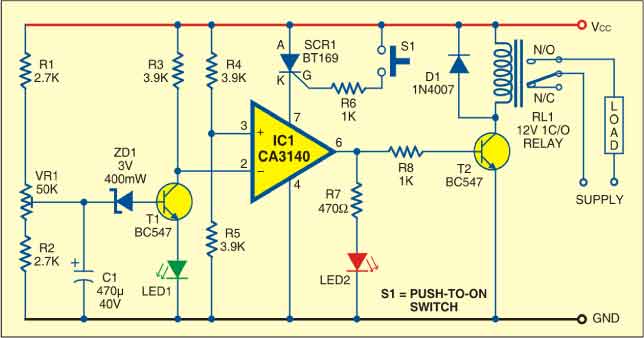
When the voltage level is normal, zener diode ZD1 breaks down and transistor T1 is forward-biased. Capacitor C1 provides time delay of a few seconds to avoid any fluctuation affecting the device during power-on. When transistor T1 conducts, the inverting input (pin 2) of IC1 goes low. However, IC1 does not give a high output as its power supply depends on the conduction of SCR1 (BT169). So manual operation is necessary to energise the relay.

When push-to-on swish S1 is pressed, SCR1 fires to provide voltage to IC1 at its pin 7. As the voltage level at the non-inverting input (pin 3) of IC1 is half of the supply voltage, its output becomes high and the relay (RL1) energises. LED2 glows to indicate the high output of IC1 and activation of relay.
When the line voltage goes below 180V, the secondary voltage of the transformer also drops, say, below 12 volts, ZD1 cease to conduct and the collector of T1 becomes high. This high voltage at the inverting input (pin 2) of IC1 makes its output low. The relay de-energises to stop power to the device.
Construction & testing
Assemble the circuit on a general purpose PCB and enclose in a suitable cabinet. Use a 12V PCB mounted relay. Provide holes for LEDs and switch S1 on the front side of the case. Connect AC power voltage to the motor (load) through the common and normally-open (N/O) contacts of the relay. After assembly and checking the circuit, switch on the circuit and wait for a few minutes. LED1 will gradually become bright due to the charging of capacitor C1. Press S1 to energise the relay. Adjust VR1 so as to make LED1 fully on. This will allow easy latching of the relay.
The article was first published in February 2010 and has recently been updated.

Thanks Mohan Kumar, for the power resumption alarm circuit. The circuit works perfectly.
But the power resumption alarm just gives a short notice sound, which can be definitely missed.
Could we increase the time duration of the sound— say about 10sec. ?
I am hoping for the reply.
where we should connect vcc??
Thanks, your article was helpful.
You are most welcome.